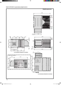
Кондиционеры Daikin UATYQ-CY1 - инструкция пользователя по применению, эксплуатации и установке на русском языке. Мы надеемся, она поможет вам решить возникшие у вас вопросы при эксплуатации техники.
Если остались вопросы, задайте их в комментариях после инструкции.
"Загружаем инструкцию", означает, что нужно подождать пока файл загрузится и можно будет его читать онлайн. Некоторые инструкции очень большие и время их появления зависит от вашей скорости интернета.


39
ENGLISH
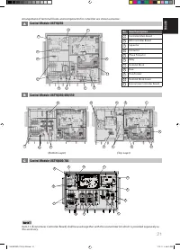
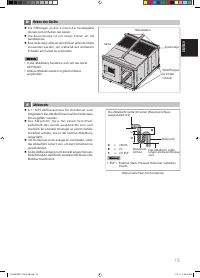
G
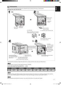
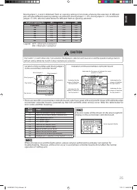
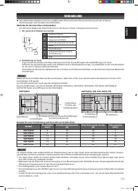
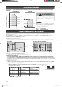
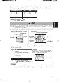
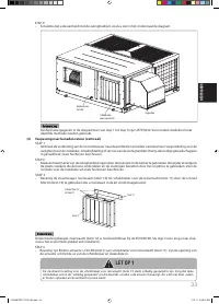
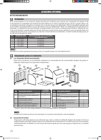
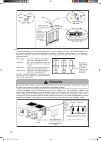
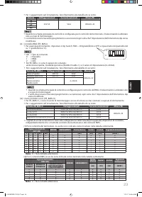
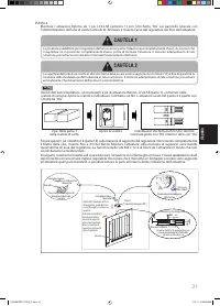
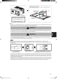
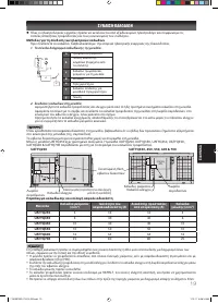
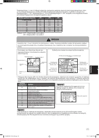
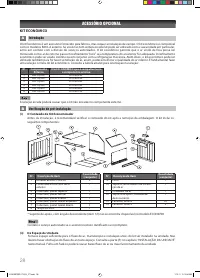
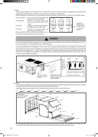
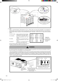
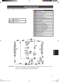
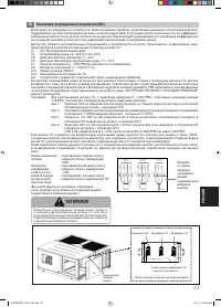
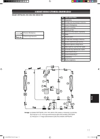
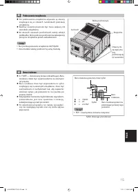
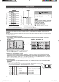
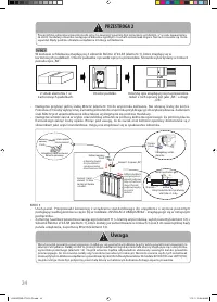
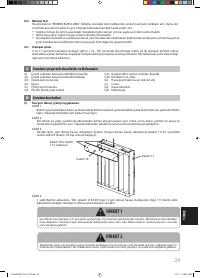
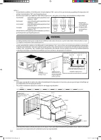
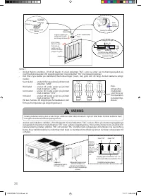
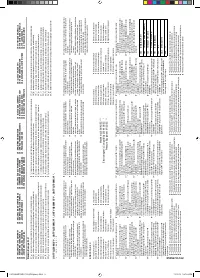
Demand Ventilation Control
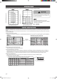
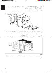
- One technique to reduce energy consumption while maintain adequate air quality is demand controlled ventilation.
Instead of setting at a fi xed air replacement rate, carbon dioxide sensor (CO
2
sensor) is used to control the rate
dynamically, based on the emissions of actual building occupants.
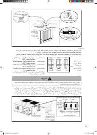
- CO
2
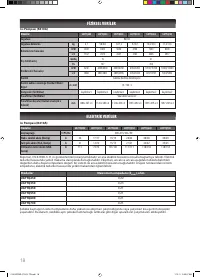
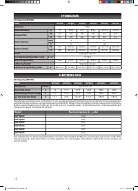
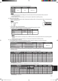
sensor is an optional component supplied in fi eld. Refer to the information below for the recommendation of CO
2
sensor selection:
(i)
Type: Duct-mounted type
(ii)
Power input: 24 VDC, 50Hz
(iii) Operating
temperature range: 0 ~ 52°C
(iv)
Ambient temperature range: -15 ~ 52ºC
(v)
Measuring range: 0 ~ 5000 PPM (depends on the application)
(vi)
Output voltage: 2 ~ 10 VDC
(vii) Wire size: AWG18
(viii) Maximum allowable current: 7A
(ix)
Compliance standards: To follow local and national regulations
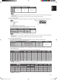
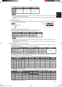
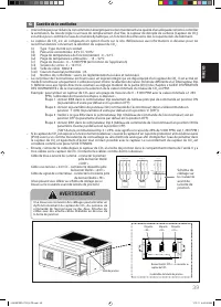
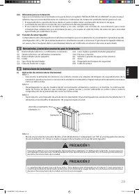
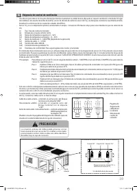
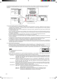
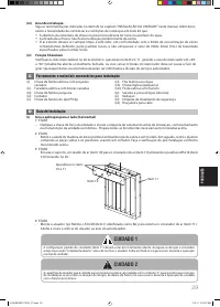
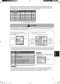
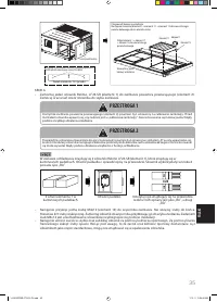
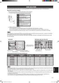
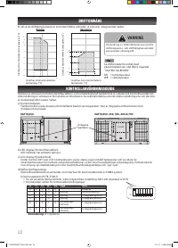
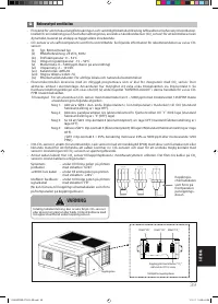
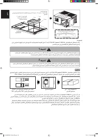
- The economizer controller comes with a build-in software which is ready with the integration of CO
2
sensor. It is activated
only in economizer mode. User is allowed to choose the diff erent threshold value selection via Dip switch 3. Refer to
hardware setting guideline provided in part (D) (v) under chapter “CONTROL OPERATION GUIDE” in this manual for CO
2
PPM level threshold value selection.
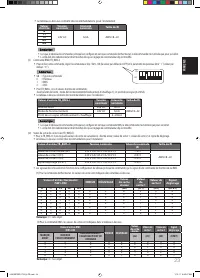
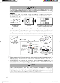
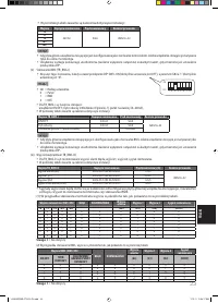
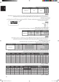
For example: To use a CO
2
sensor with measuring range from 0 ~ 5000 PPM with the threshold value at 1250PPM, user
needs to do the following steps:-
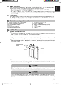
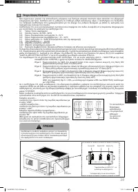
Step 1: Enable SW4 in the only Dip Switch in controller main board to ON position (default factory
setting is in OFF position).
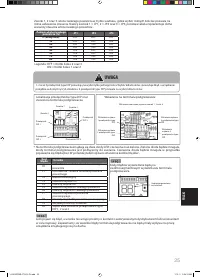
Step 2: Enable panel parameter G6 (economizer control) in remote controller to ‘1’ (ON) position (default
factory setting is in ‘0’ (OFF) position).
Step 3: Ensure SW2 in Dip Switch 4 (Economizer controller board) is in OFF position (default factory
setting is in OFF position).
Step 4: Enable SW1 in Dip Switch 3 (Economizer controller board) to ON position (default factory setting
is in OFF position).
{ SW1 in Dip Switch 3 = 25%, by calculation means 25% of 5000 PPM or equivalent to 1250
PPM }.
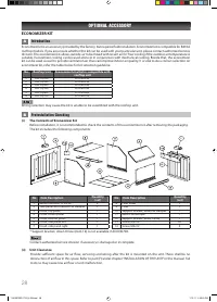
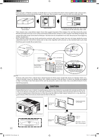
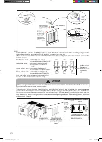
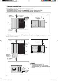
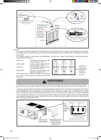
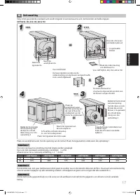
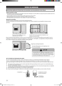
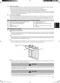
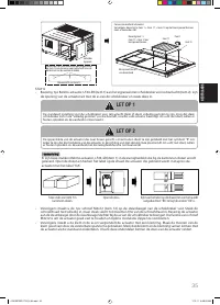
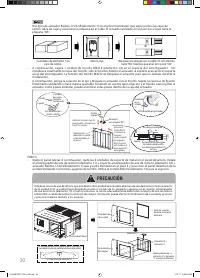
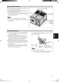
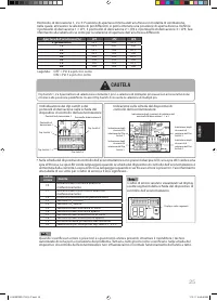
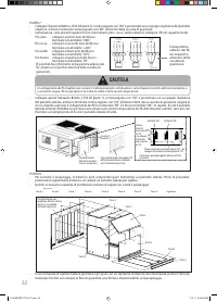
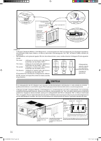
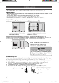
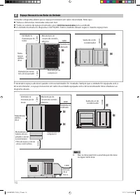
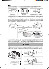
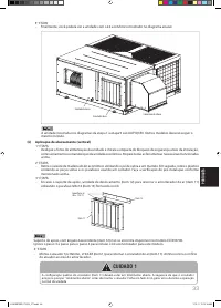
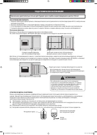
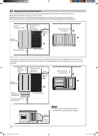
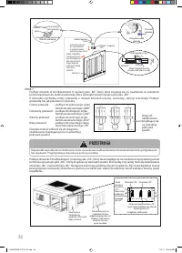
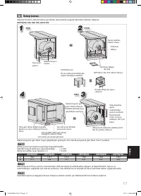
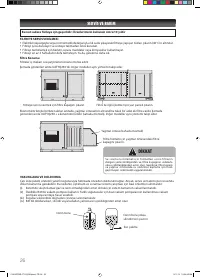
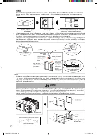
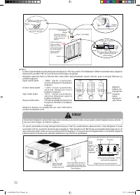
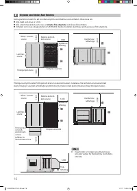
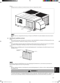
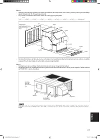
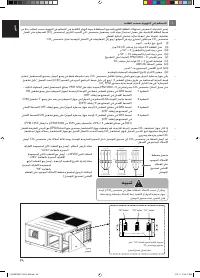
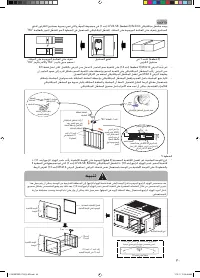
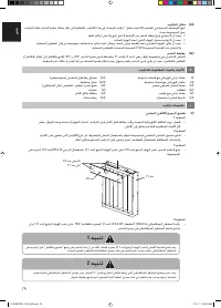
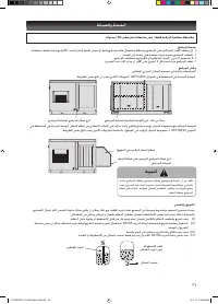
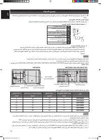
- If the CO
2
sensor is exposed to outdoor environment, cover the sensor with a splash proof (IPX4) box with screw as
locking mechanism or similar method to prevent water from entering into the CO
2
sensor and also to avoid possible
contact with the sensor. The connection of CO
2
sensor is considered a LIVE part.
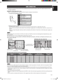
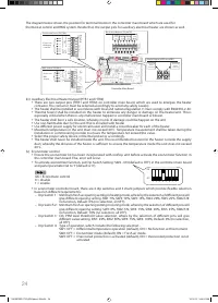
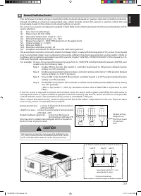
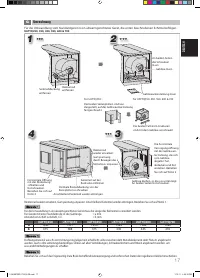
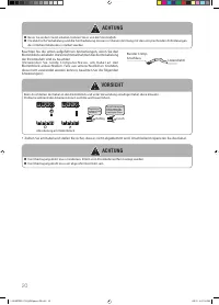
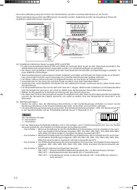
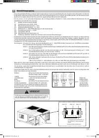
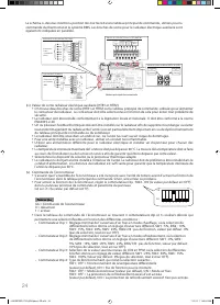
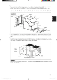
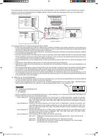
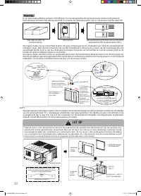
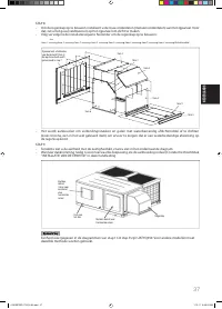
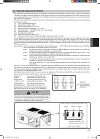
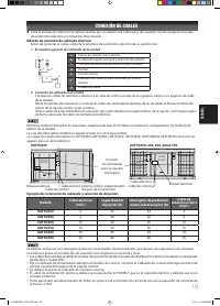
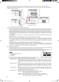
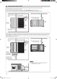
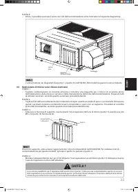
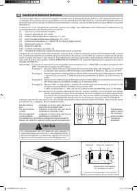
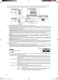
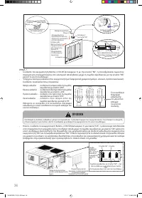
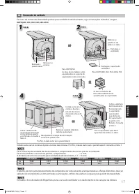
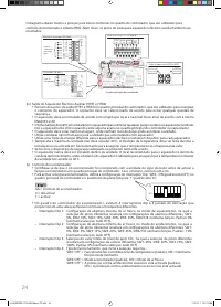
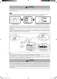
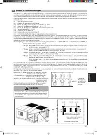
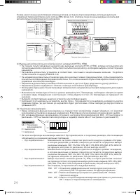
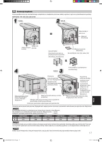
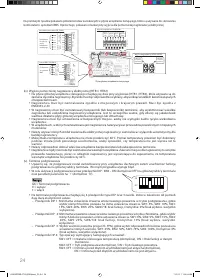
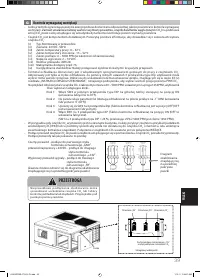
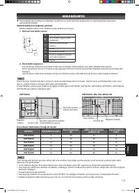
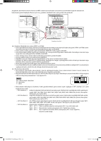
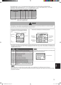
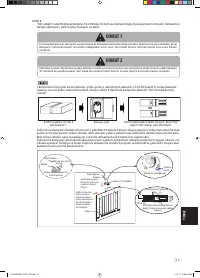
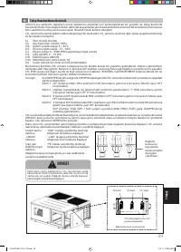
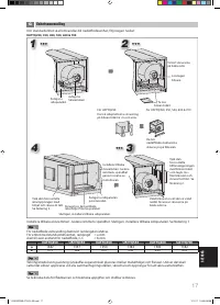
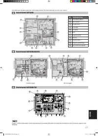
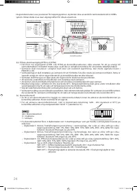
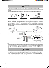
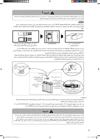
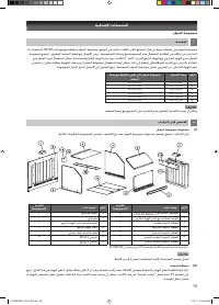
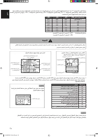
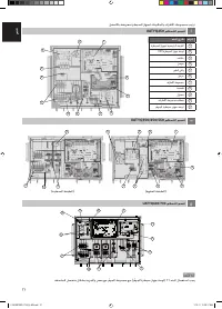
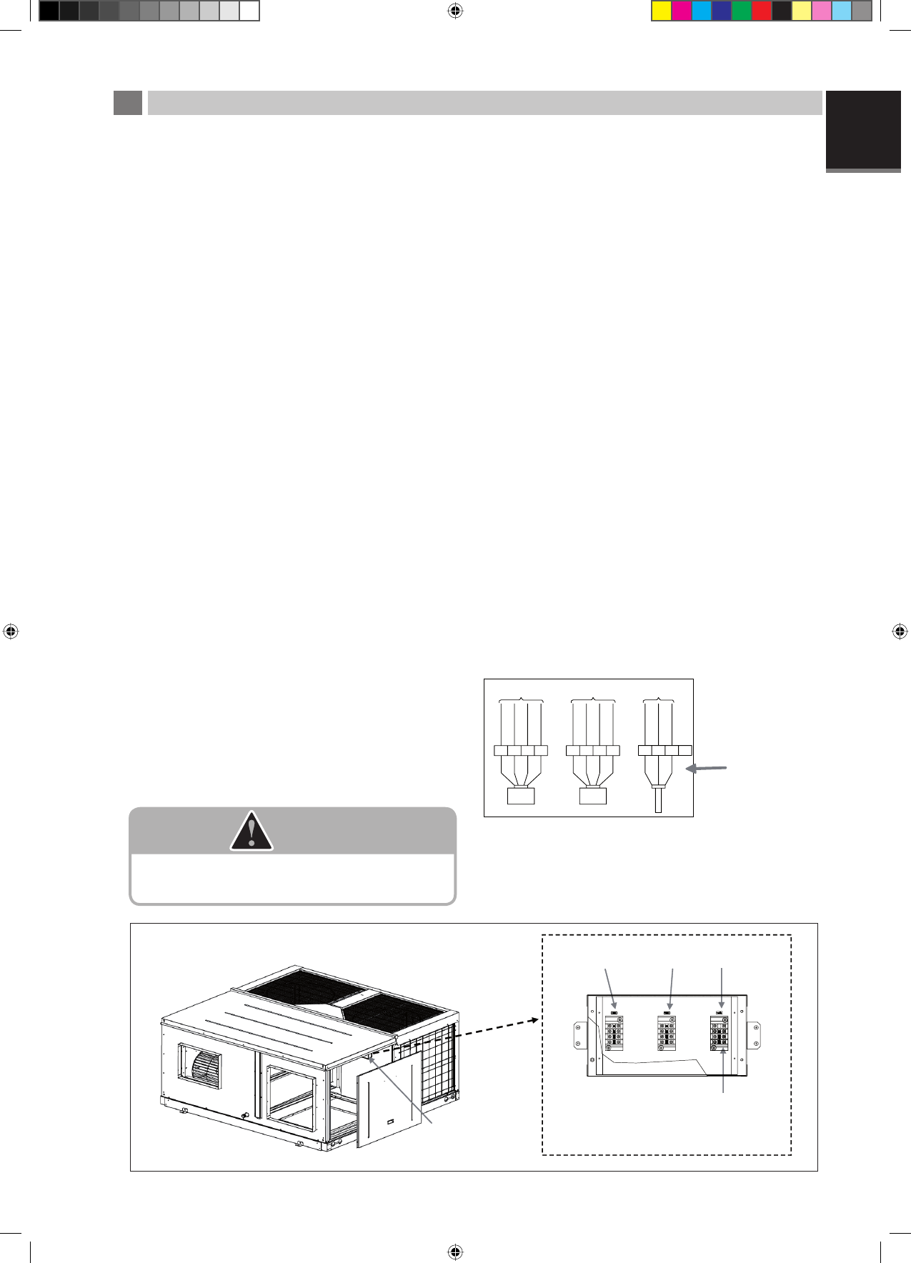
- Then, connect the wire from CO
2
sensor to the junction box in the indoor compartment of the unit. There are three
wires on CO
2
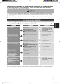
sensor. Connect the wires as below:
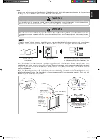
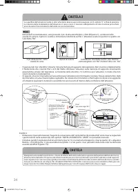
System ground wire - connect to fi rst pole of terminal block
with label ‘GND’.
+24VDC live wire - connect to second pole of terminal block
with label ‘+24V’.
Output/ feedback signal wire - connect to third pole of
terminal block with label ‘FB’.
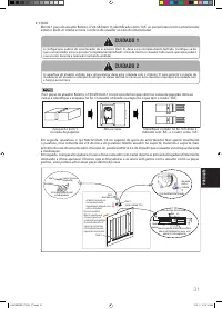
(You may refer to sticker wiring diagram which is located on
the front cover of junction box.)
Sticker wiring
diagram on
the front cover
of junction
box
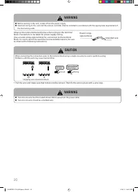
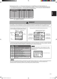
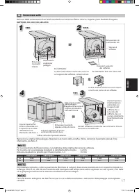
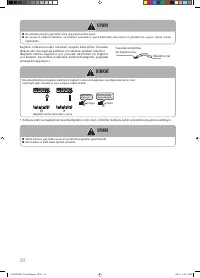
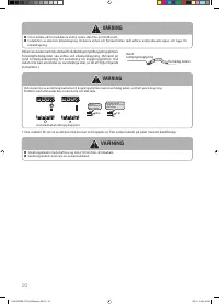
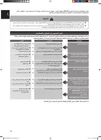
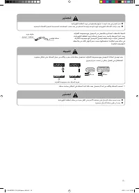
CAUTION
Wrong wiring connection may cause the malfunction on
CO
2
sensor or economizer controller board or both. Tie the
wires with releasable cable ties under the junction box.
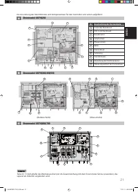
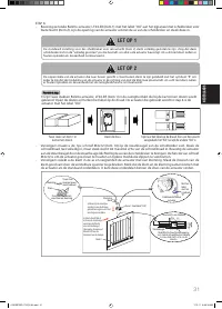
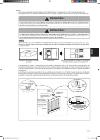
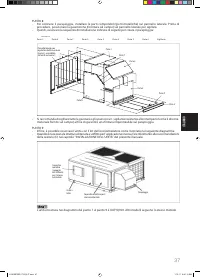
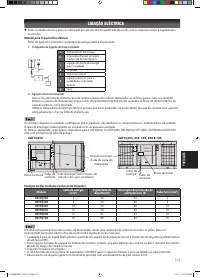
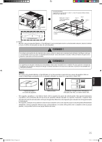
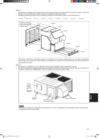
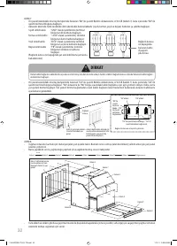
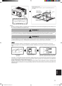
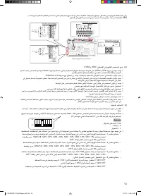
Label ‘RA’
Junction
box
Label ‘OA’
Label ‘CO
2
’
Terminal block with label ‘CO
2
’ - to be
connected with CO
2
sensor.
Detail view of junction box
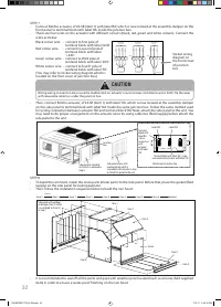
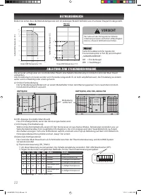
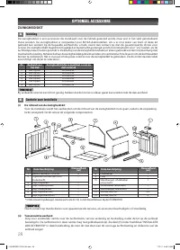
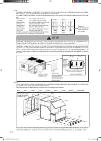
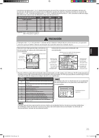
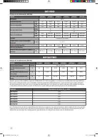
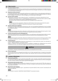
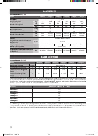
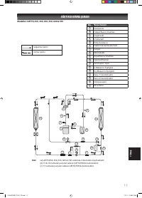
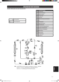
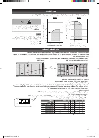
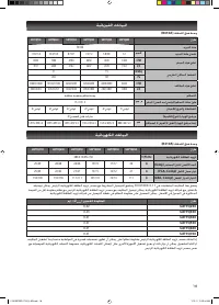
TO PCB3 (ECO)
CN_ACT_RA
TO PCB3 (ECO)
CN_ACT_OA
TO PCB3 (ECO)
CN_C02
TB RA
TB OA
TB C02
BLA
CK
RED
GREEN
WHITE
BLA
CK
RED
GREEN
WHITE
BLA
CK
RED
WHITE
GND +24V DCV
FB
GND +24V DCV
FB
GND +24V
FB
ACTUATOR RA
ACTUATOR OA
C02 SENSOR
1 IM 5RTBR-0710(2)-EN.indd 39
1 IM 5RTBR-0710(2)-EN.indd 39
1/10/11 3:39:37 PM
1/10/11 3:39:37 PM


