Кондиционеры Daikin UATYQ-CY1 - инструкция пользователя по применению, эксплуатации и установке на русском языке. Мы надеемся, она поможет вам решить возникшие у вас вопросы при эксплуатации техники.
Если остались вопросы, задайте их в комментариях после инструкции.
"Загружаем инструкцию", означает, что нужно подождать пока файл загрузится и можно будет его читать онлайн. Некоторые инструкции очень большие и время их появления зависит от вашей скорости интернета.


23
ENGLISH
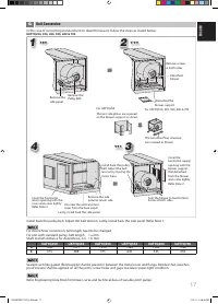
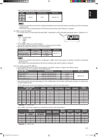
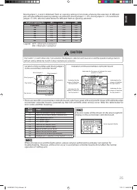
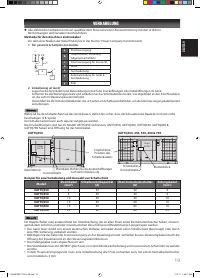
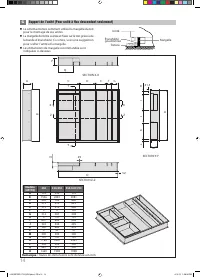
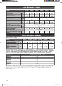
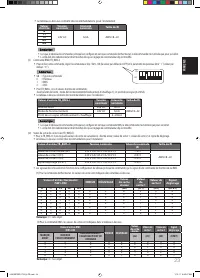
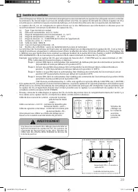
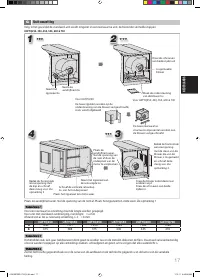
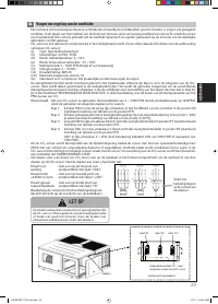
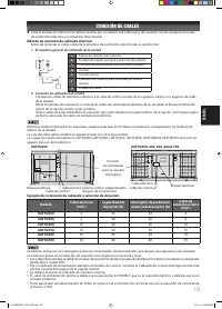
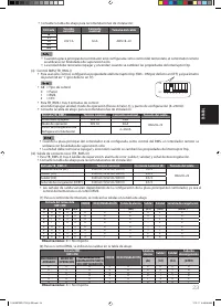
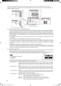
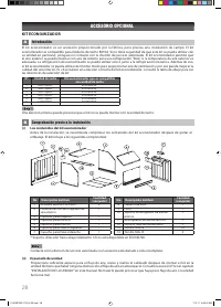
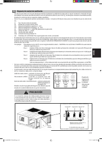
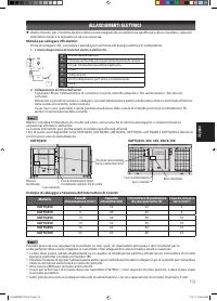
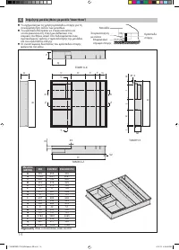
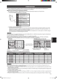
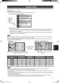
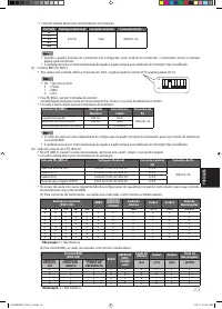
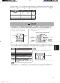
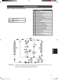
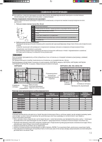
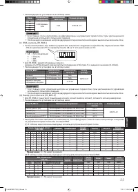
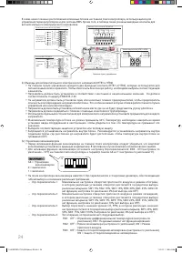
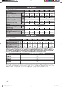
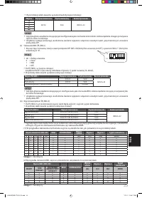
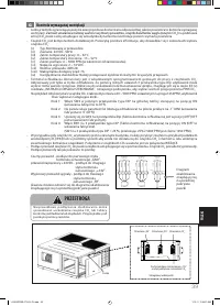
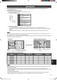
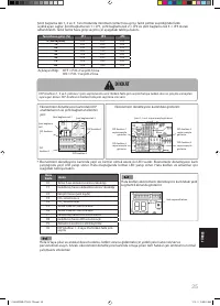
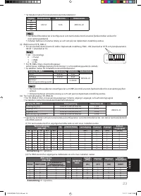
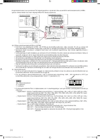
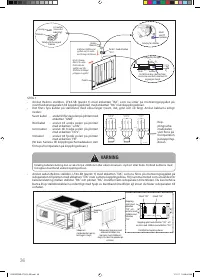
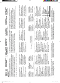
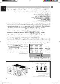
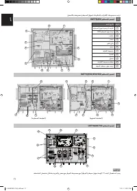
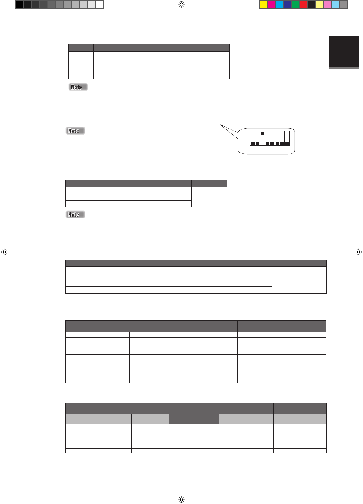
Refer table below for installation recommendations:
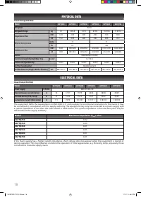
Input
Rated voltage
Rated current
Wire size
G
24V AC
5mA
AWG18~22
Y1
Y2
W1
W2
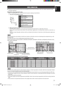
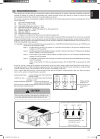
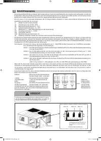
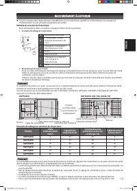
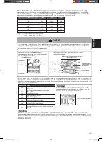
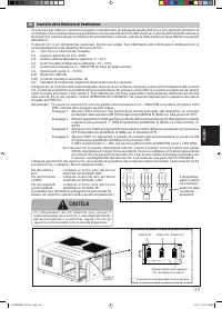
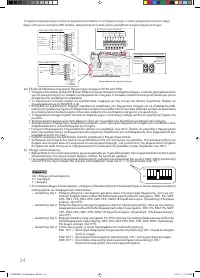
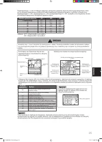
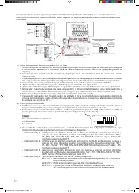
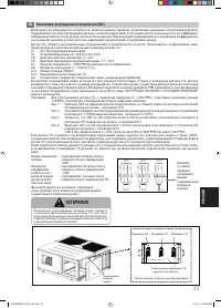
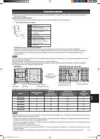
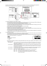
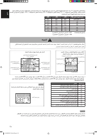
When the controller main board is confi gured as thermostat control, the remote controller is used for monitoring
purpose only.
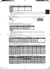
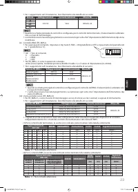
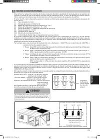
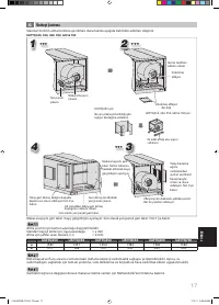
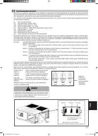
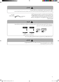
Unit needs to be restarted (power off and on) whenever dip switch setting is changed.
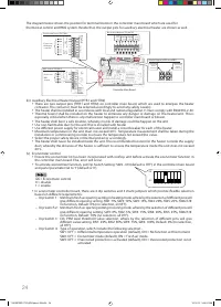
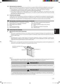
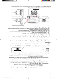
(ii) BMS control ( TB_BMS-I)
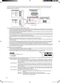
To use this control, set Dip Switch Setting: SW3 - ON (default is OFF) and panel parameter G8 to ‘1’ (default is ‘0’).
G8 =
Control
Type
0 =
Panel
1 =
BMS
2 =
DEC
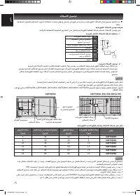
For TB_BMS-I, there are 3 control inputs:
unit on/off ; operating mode (cool-0/heat-1); and set point (4~20mA).
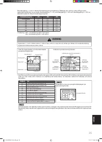
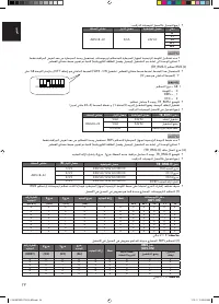
Refer below table for installation recommendations:
Input TB_BMS-I
Rated voltage
Rated current
Wire size
On/Off 24V
AC
5mA
AWG18~22
Operating mode
24V AC
5mA
Cool/Heat set point
-
4~20mA
When the controller main board is confi gured as BMS control, the remote controller is used for monitoring
purpose only.
Unit needs to be restarted (power off and on) whenever dip switch setting is changed.
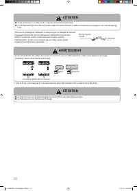
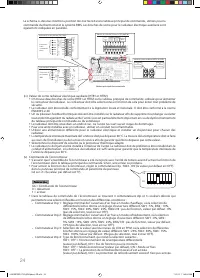
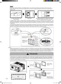
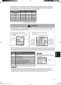
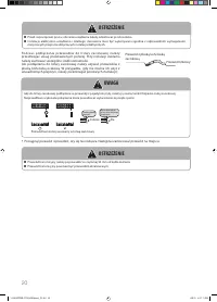
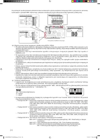
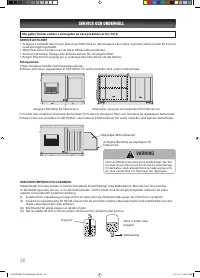
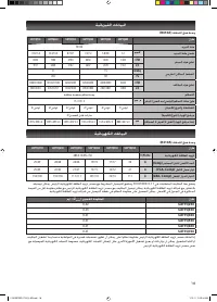
(iii) Dry contact output ( TB_BMS-O)
For TB_BMS-O, there are 4 monitoring outputs: error alarm; output1; output2; and defrost signal.
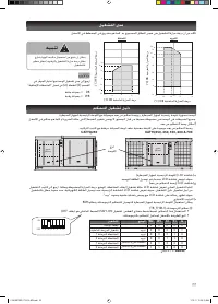
Refer table below for installation recommendations:
Input TB_BMS-O
Rated voltage
Rated current (A)
Wire size
Alarm output (AL)
230V AC/125V AC/30V DC
1/3/3
AWG18~22
Output1 (O1)
230V AC/125V AC/30V DC
2/3/3
Output2 (O2)
230V AC/125V AC/30V DC
3/3/3
Defrost signal (DFRT )
230V AC/125V AC/30V DC
4/3/3
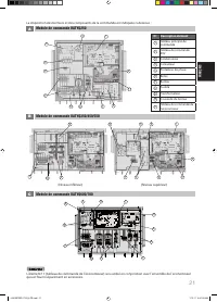
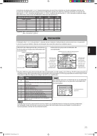
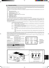
The output signals will vary depending on the confi guration of controller main board, whether it is thermostat
control or BMS control.
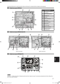
(1) For thermostat control, the outputs are indicated as shown in the table below.
Thermostat input
(SW1-ON)
ERROR
DEFROST
Alarm output
Output1
Output2
Defrost
signal
G
Y1
Y2
W1
W2
(AL)
(O1)
(O2)
(DFRT)
0
0
0
0
0
X
X
X
0
0
X
1
0
0
0
0
X
X
X
0
1
X
X
1
0
X
X
X
X
X
1
0
X
X
1
1
X
X
X
X
X
1
0
X
X
0
X
1
0
X
X
X
1
1
X
X
0
X
1
1
X
X
X
1
1
X
X
X
X
X
X
1
X
1
X
X
X
X
X
X
X
X
X
1
X
X
X
1
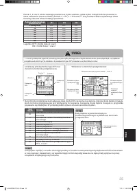
Remark:
X = Don’t care.
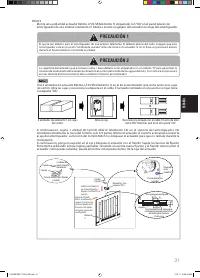
(2) For BMS control, the outputs are indicated as shown in the table below.
BMS input
(SW3-ON)
ERROR
DEFROST
Alarm
output
Output1
Output2
Defrost
signal
ON/OFF
OPERATING
MODE
COOL/HEAT
SET POINT
(AL)
(O1)
(O2)
(DFRT)
0
0
X
X
X
X
0
0
X
0
1
X
X
X
X
0
1
X
1
0
X
X
X
X
1
0
X
1
1
X
X
X
X
1
1
X
X
X
X
1
X
1
X
X
X
X
X
X
X
1
X
X
X
1
Remark:
X = Don’t care.
ü
ü
ü
ü
ü
ü
ü
ü
ü
ü
ü
ü
1 2 3 4 5 6 7
8
ON
OFF
1 IM 5RTBR-0710(2)-EN.indd 23
1 IM 5RTBR-0710(2)-EN.indd 23
1/10/11 3:38:56 PM
1/10/11 3:38:56 PM


