Кондиционеры Daikin UATYQ-CY1 - инструкция пользователя по применению, эксплуатации и установке на русском языке. Мы надеемся, она поможет вам решить возникшие у вас вопросы при эксплуатации техники.
Если остались вопросы, задайте их в комментариях после инструкции.
"Загружаем инструкцию", означает, что нужно подождать пока файл загрузится и можно будет его читать онлайн. Некоторые инструкции очень большие и время их появления зависит от вашей скорости интернета.


19
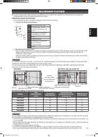
ENGLISH
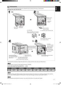
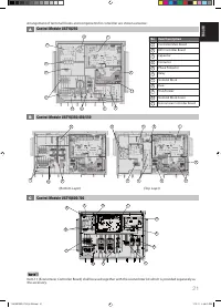
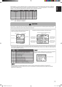
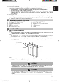
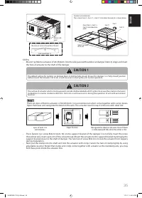
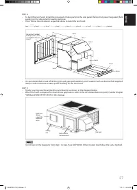
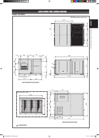
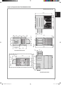
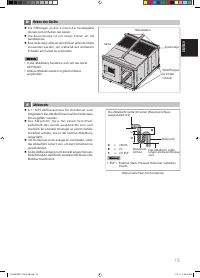
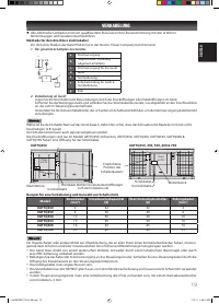
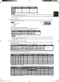
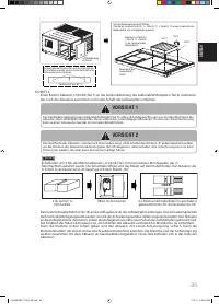
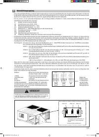
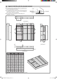
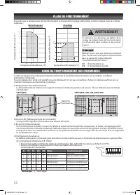
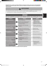
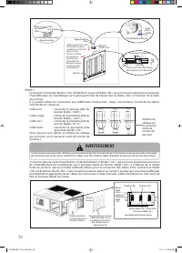
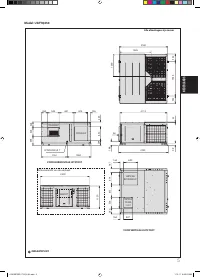
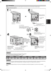
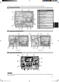
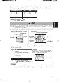
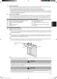
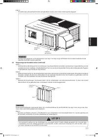
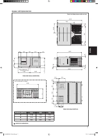
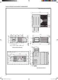
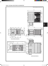
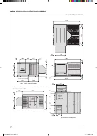
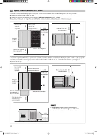
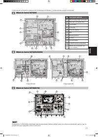
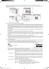
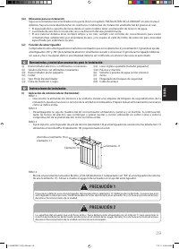
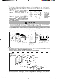
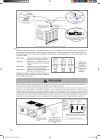
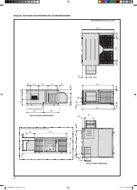
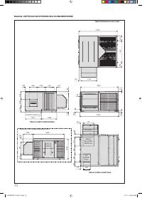
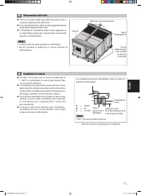
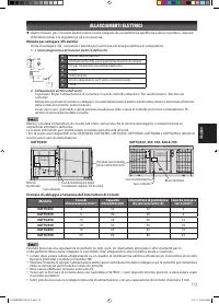
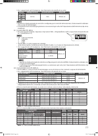
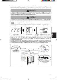
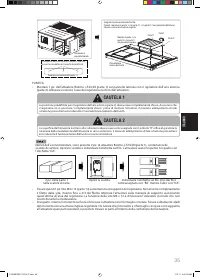
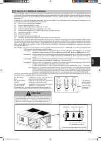
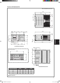
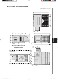
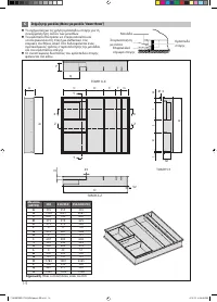
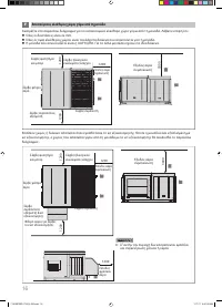
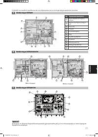
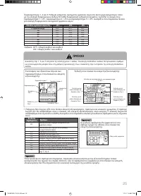
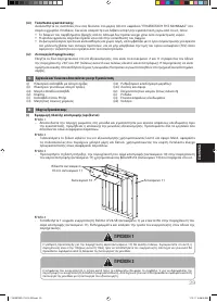
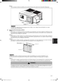
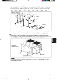
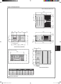
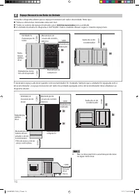
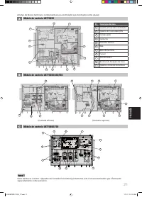
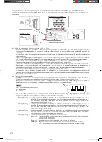
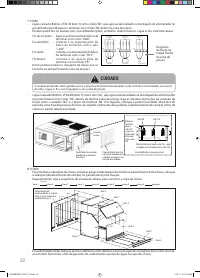
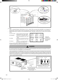
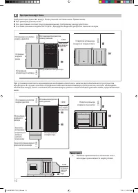
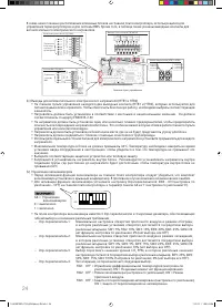
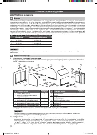
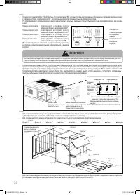
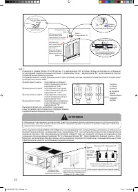
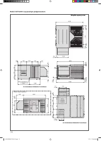
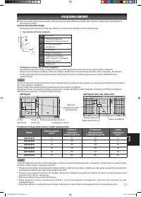
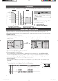
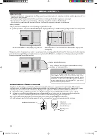
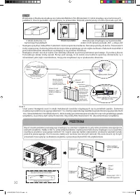
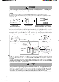
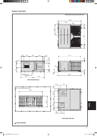
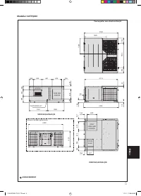
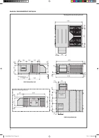
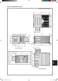
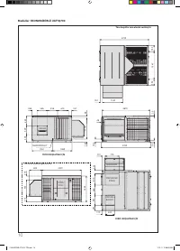
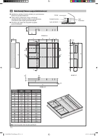
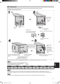
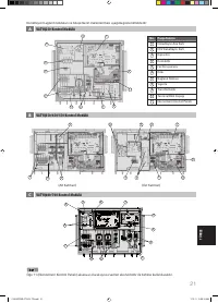
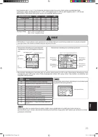
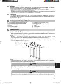
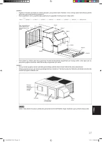
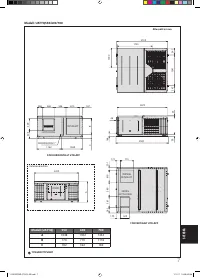
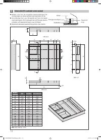
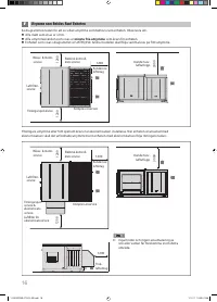
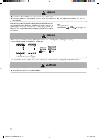
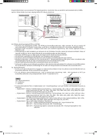
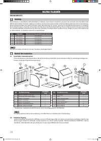
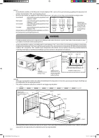
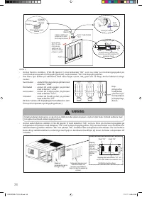
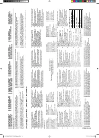
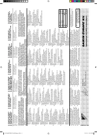
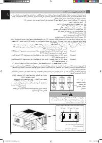
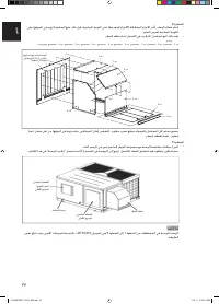
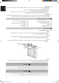
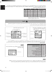
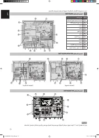
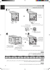
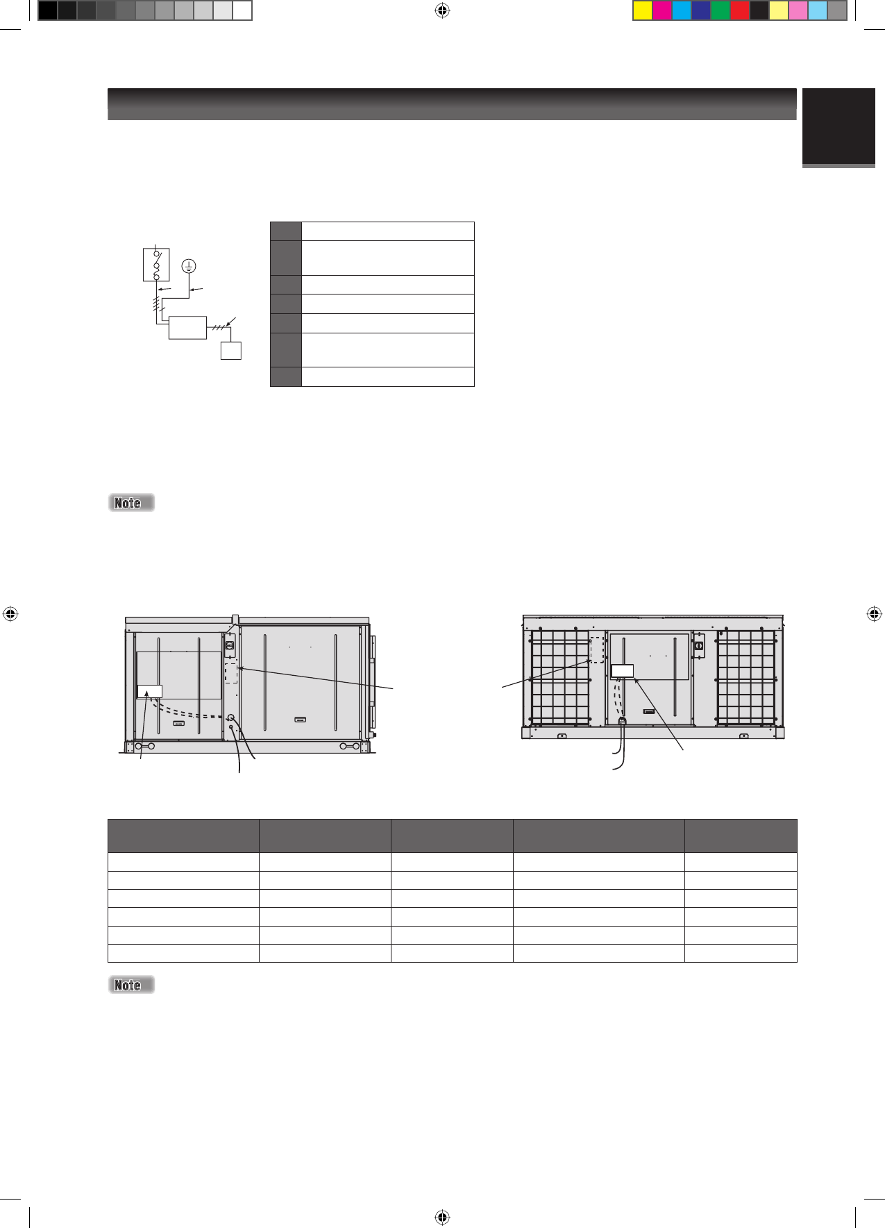
Recommended
switch box position
Terminal block
Terminal block
Power cable (seal off the knockout
holes after installation)
CONTROL
BOX
CONTROL
BOX
Control wire
Power cable
Control wire
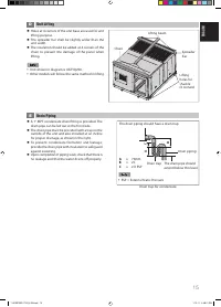
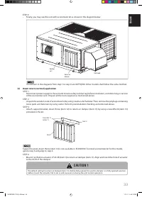
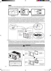
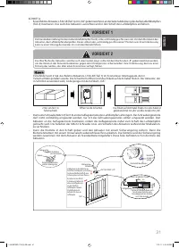
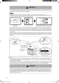
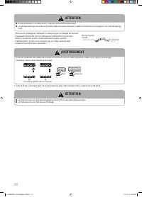
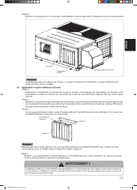
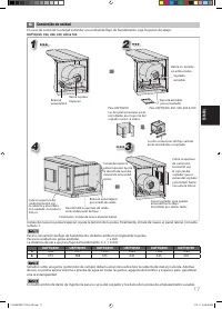
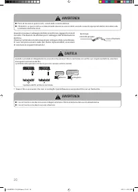
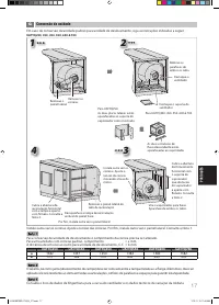
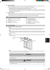
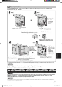
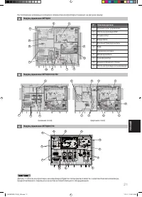
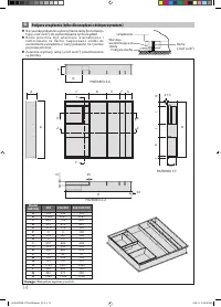
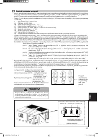
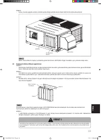
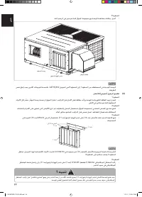
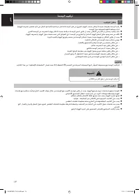
While installing the circuit breaker onto the unit, make sure that the screws do not damage the components (e.g. coil)
inside the unit.
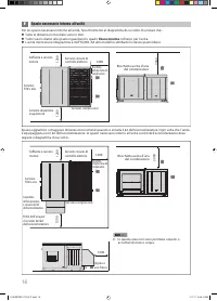
The switch box also can be installed without attaching to the unit.
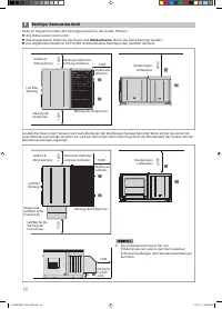
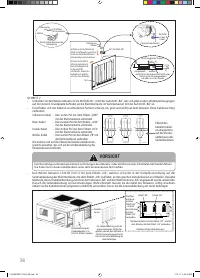
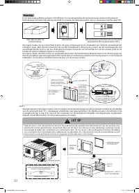
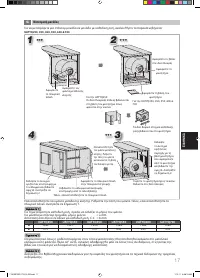
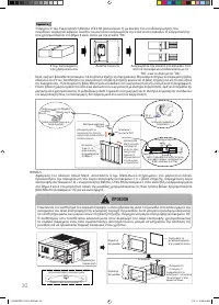
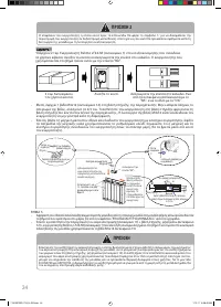
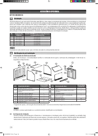
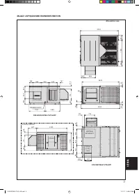
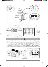
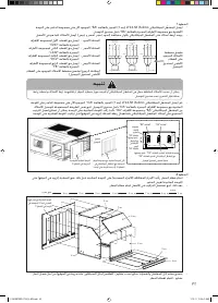
The knockout holes are only available in UATYQ250; UATYQ350, UATYQ450, UATYQ550, UATYQ600 & UATYQ700 comes
with a power cable hole.
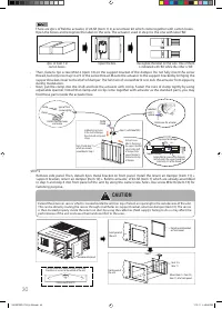
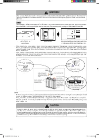
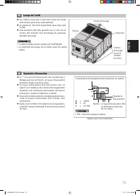
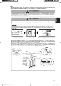
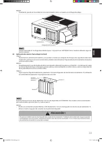
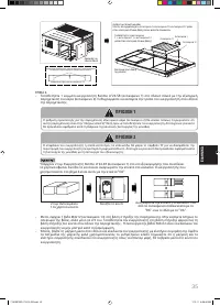
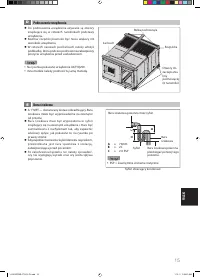
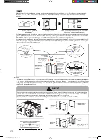
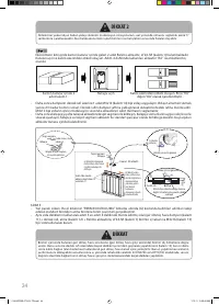
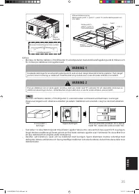
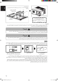
A main switch or other means for disconnection, having a contact separation in all poles, must be incorporated in fi xed
wiring in accordance with local and national legislation.
The unit is to be wired directly from an electrical distribution board either by a circuit breaker (preferred) or HRC fuse.
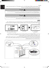
Fix the power supply wiring to control module. Connect control wiring to control terminal block through the control
box’s hole.
Earth wiring must be connected.
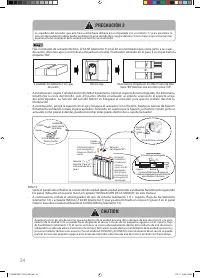
The power supply cord must be equivalent to H07RN-F which is the minimum requirement, and to be used in protective
tube.
There must be an all pole disconnection in the supply mains with a contact separation of at least 3mm.
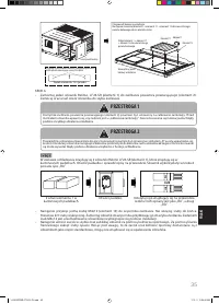
ü
ü
ü
ü
ü
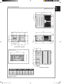
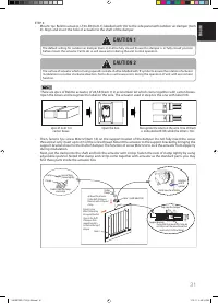
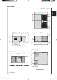
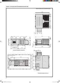
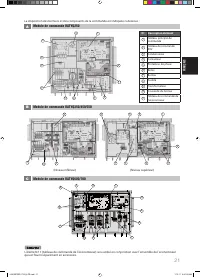
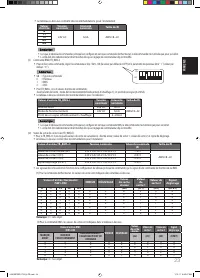
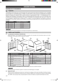
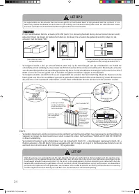
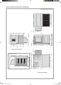
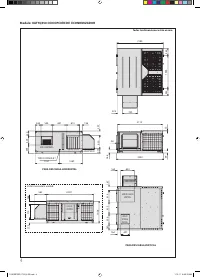
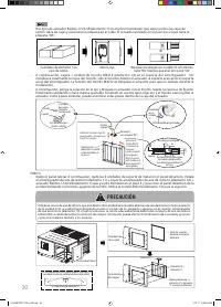
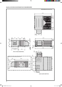
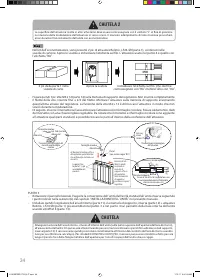
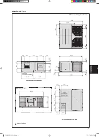
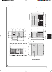
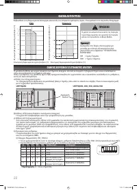
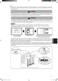
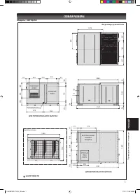
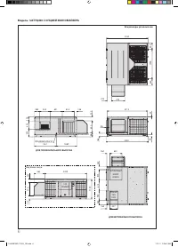
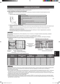
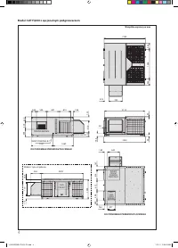
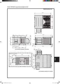
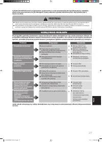
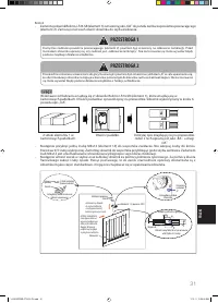
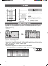
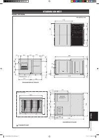
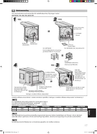
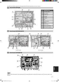
UATYQ250
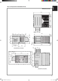
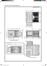
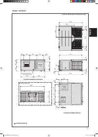
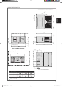
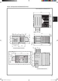
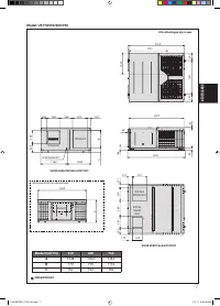
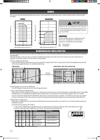
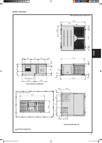
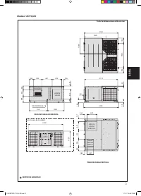
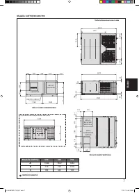
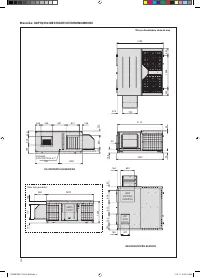
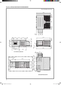
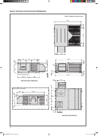
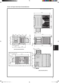
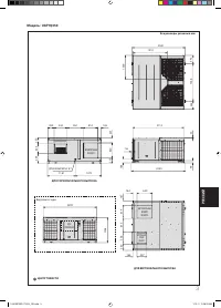
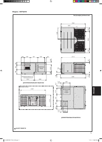
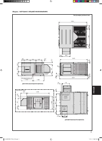
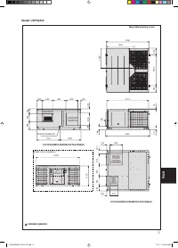
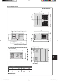
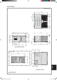
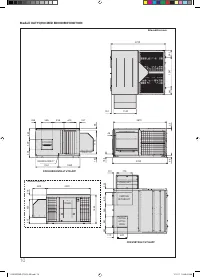
UATYQ350, 450, 550, 600 & 700
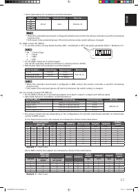
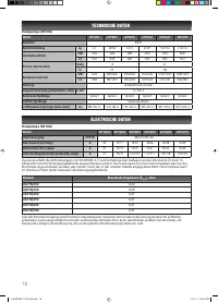
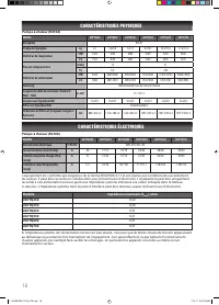
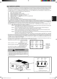
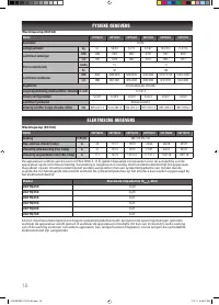
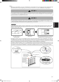
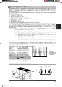
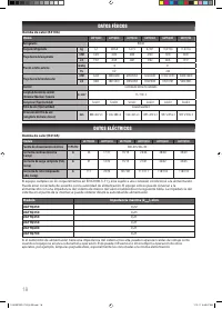
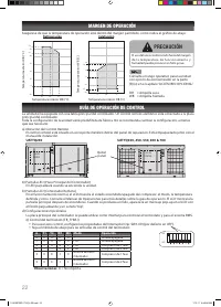
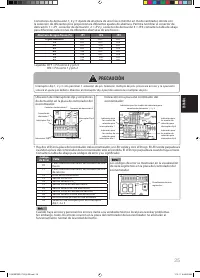
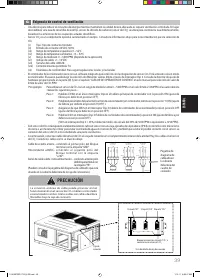
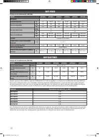
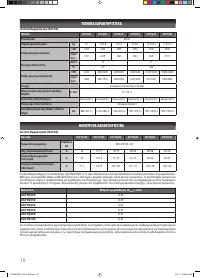
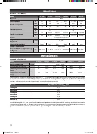
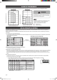
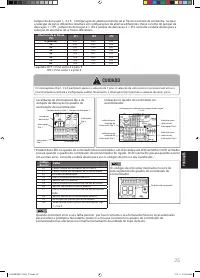
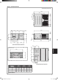
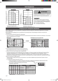
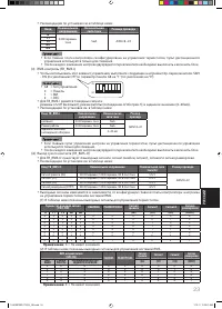
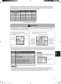
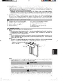
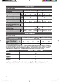
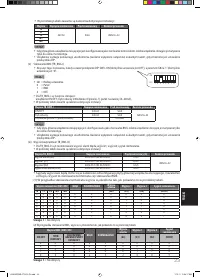
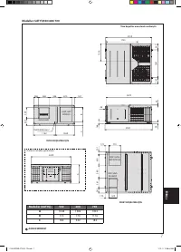
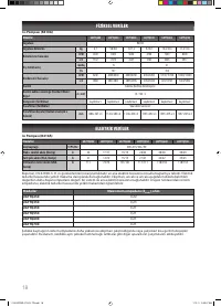
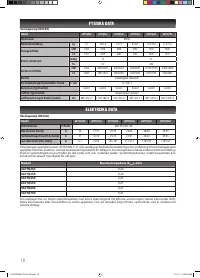
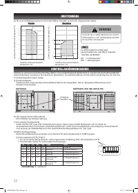
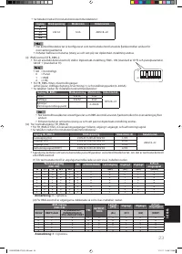
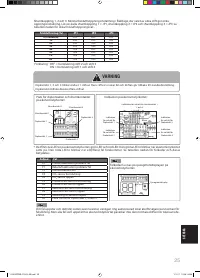
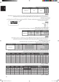
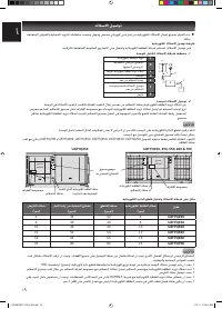
Wiring Example And Selection Of Circuit Breaker
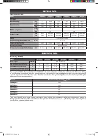
Model
Power cable
(mm
2
)
Breaker
capacity (A)
Over current
protection switch (A)
Earth cable
(mm
2
)
UATYQ250
4
32
32
4
UATYQ350
6
40
40
6
UATYQ450
10
40
40
10
UATYQ550
10
50
50
10
UATYQ600
16
63
63
16
UATYQ700
25
80
80
25
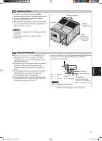
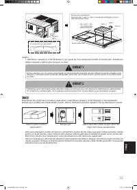
All electrical work must be carried out by qualifi ed electrician and accordance with local supply requirement and
associate regulation.
l
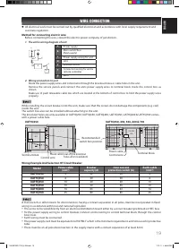
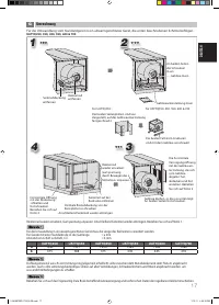
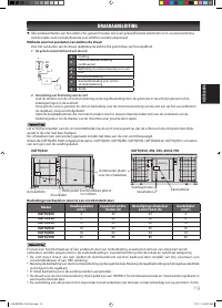
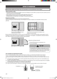
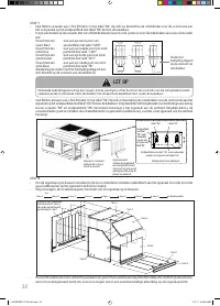
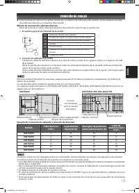
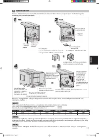
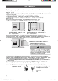
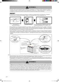
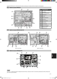
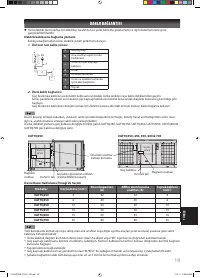
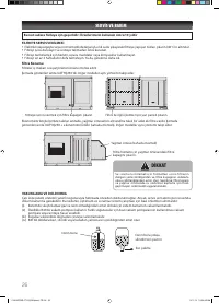
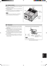
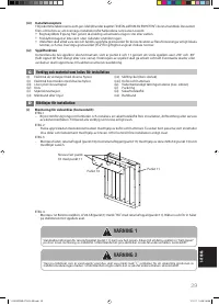
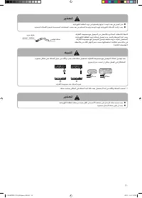
Method for connecting electric wire
Before connecting the wire, consult the electric power company of jurisdiction.
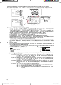
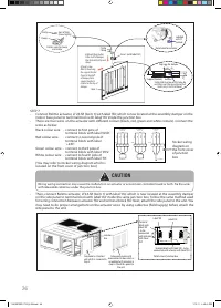
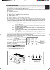
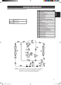
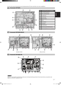
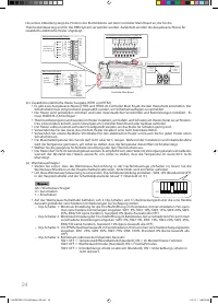
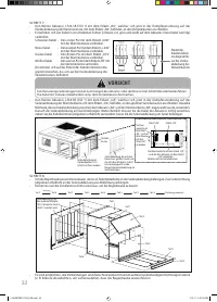
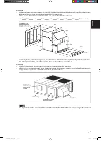
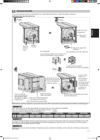
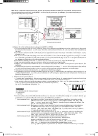
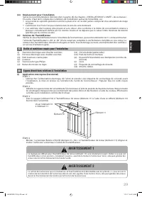
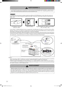
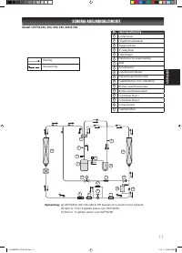
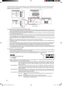
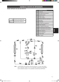
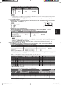
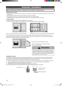
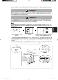
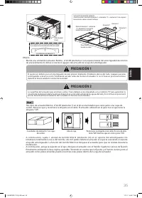
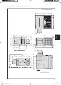
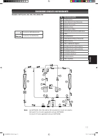
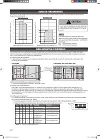
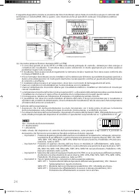
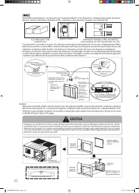
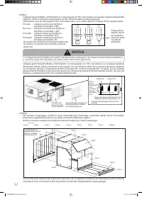
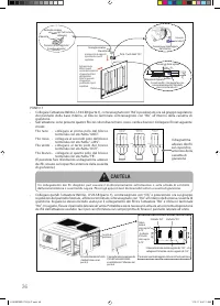
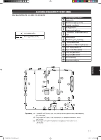
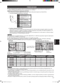
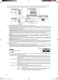
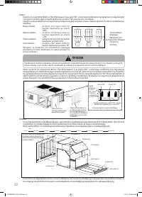
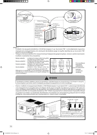
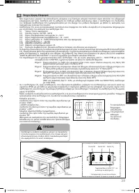
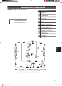
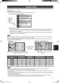
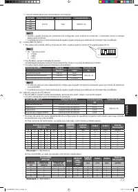
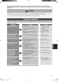
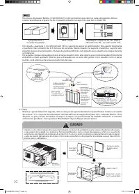
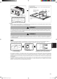
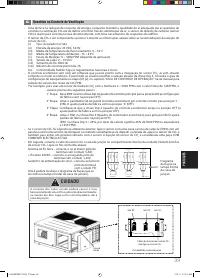
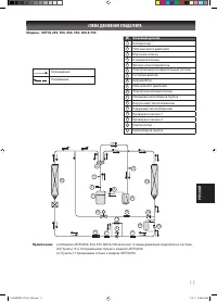
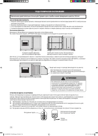
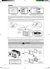
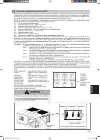
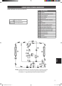
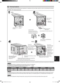
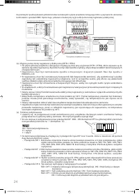
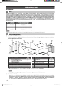
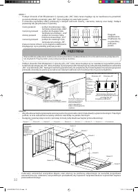
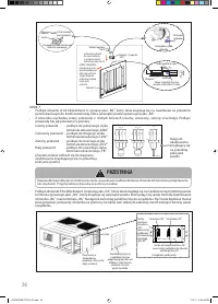
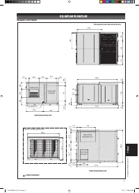
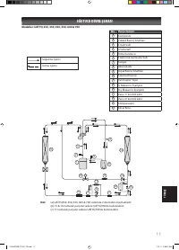
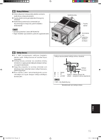
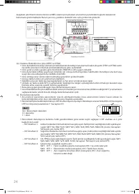
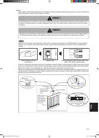
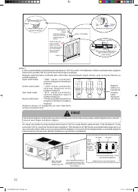
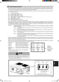
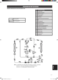
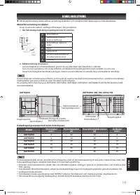
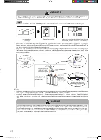
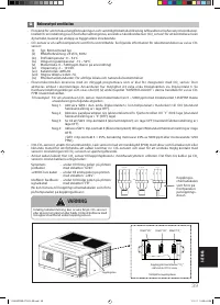
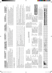
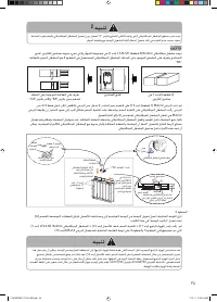
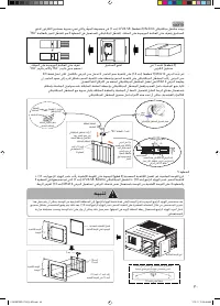
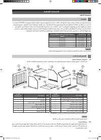
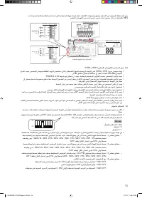
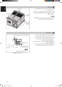
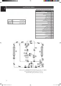
1. The entire wiring diagram of unit
PE
a
b
c
d
g
e
f
a
Power supply
b
Main switch/fuse
(fi eld supply)
c
Power supply wiring for unit
d
Unit
e
Remote control
f
Connection wiring for unit &
remote controller
g
Earth
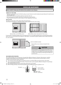
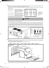
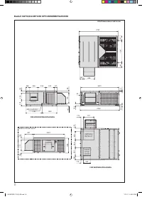
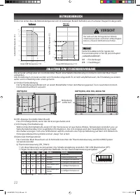
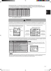
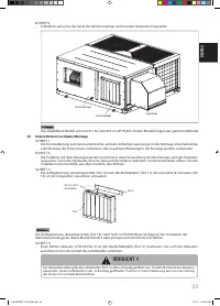
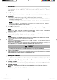
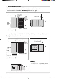
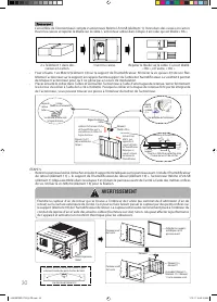
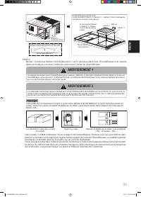
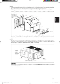
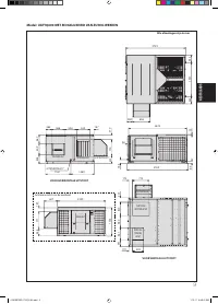
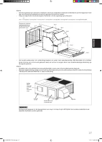
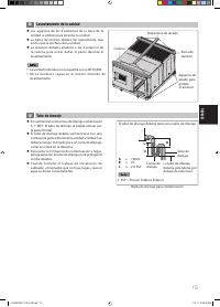
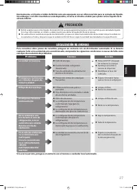
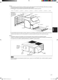
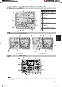
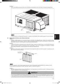
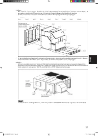
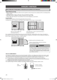
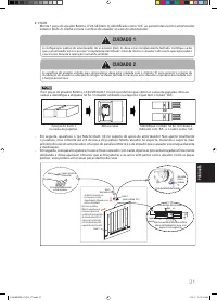
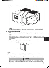
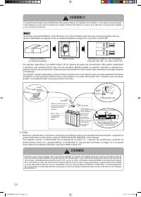
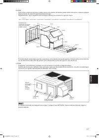
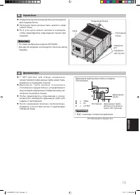
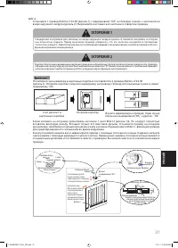
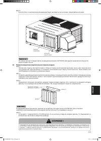
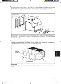
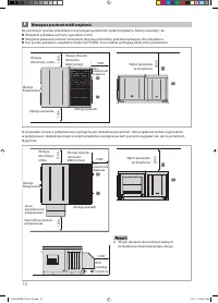
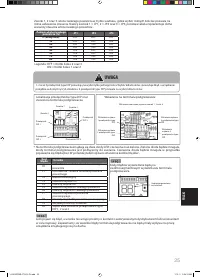
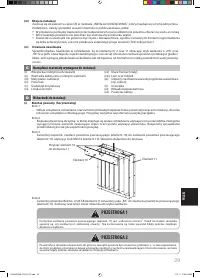
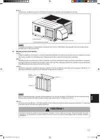
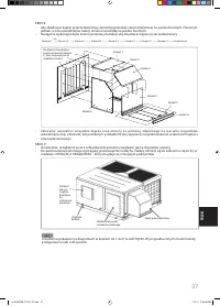
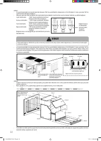
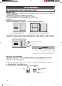
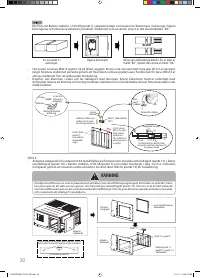
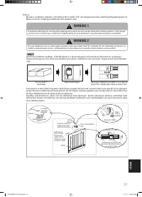
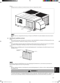
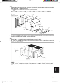
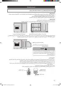
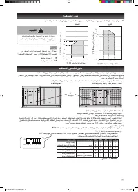
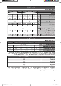
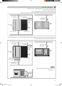
2. Wiring connection to unit
Route the power supply wires and control wire through the knockout holes or cable holes in the unit.
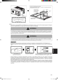
Remove the service panels and connect the units power supply wires to terminal block inside the control box, as
shown.
Make use of push releasable cable ties which are located at the bottom of control box to hold the power supply wires
properly.
WIRE CONNECTION
1 IM 5RTBR-0710(2)-EN.indd 19
1 IM 5RTBR-0710(2)-EN.indd 19
1/10/11 3:38:38 PM
1/10/11 3:38:38 PM


