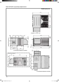
Кондиционеры Daikin UATYQ-CY1 - инструкция пользователя по применению, эксплуатации и установке на русском языке. Мы надеемся, она поможет вам решить возникшие у вас вопросы при эксплуатации техники.
Если остались вопросы, задайте их в комментариях после инструкции.
"Загружаем инструкцию", означает, что нужно подождать пока файл загрузится и можно будет его читать онлайн. Некоторые инструкции очень большие и время их появления зависит от вашей скорости интернета.


24
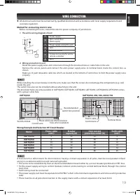
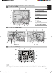
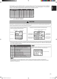
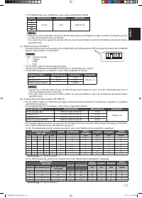
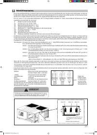
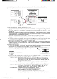
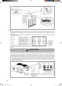
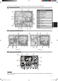
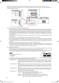
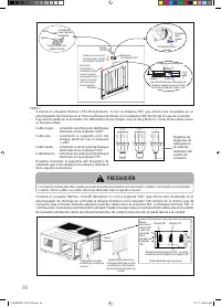
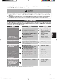
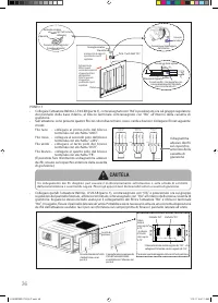
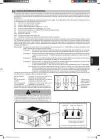
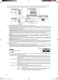
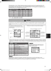
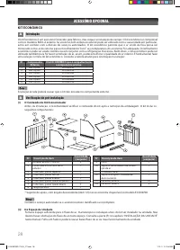
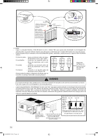
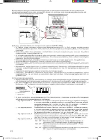
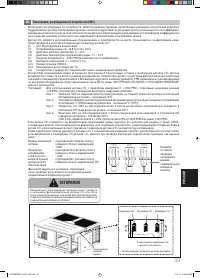
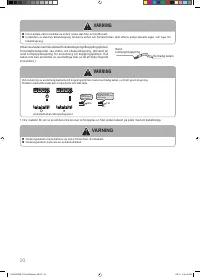
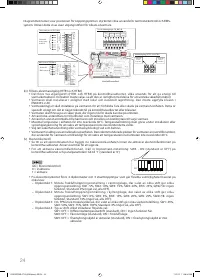
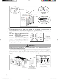
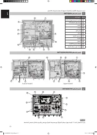
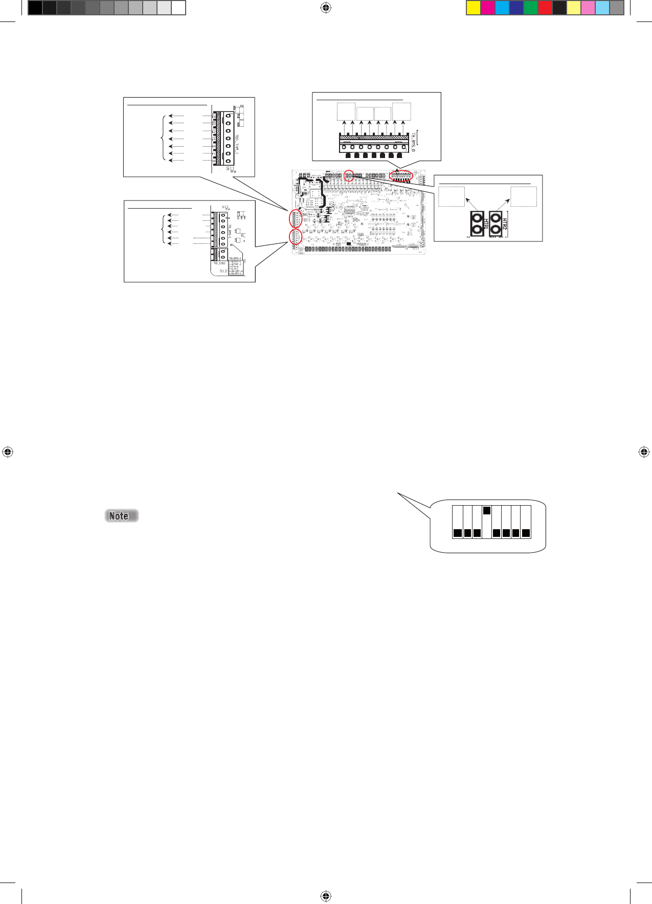
Thermostat Control ( TB_THM-l)
Connect to
third party
controller
BMS System ( TB_BMS-l)
Connect to
BMS
System
Dry Contact Outputs ( TB_BMS-O)
Controller Main Board
Alarm
output
(AL)
Output
1 (O1)
Output
2 (O2)
Defrost
signal
(DFRT )
Heater Output (HTR1 and HTR2)
Connect to
heater
contactor
Connect to
heater
contactor
Unit
on/
off
C
ool/
Heat
mode
selec
t
C
ool/
Heat
set
point
Supply
V
oltage
24V A
C
T
hermostat c
ontr
ol
inputs
(G, Y1, Y2,
W1,
W2)
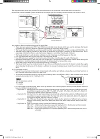
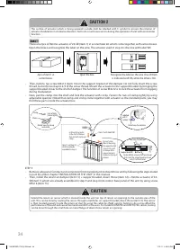
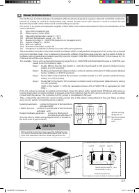
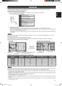
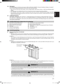
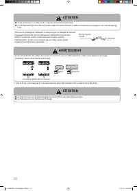
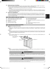
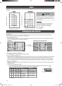
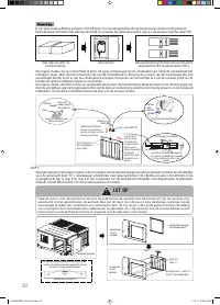
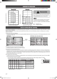
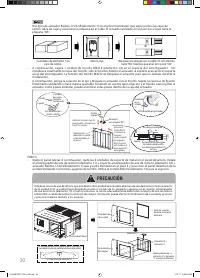
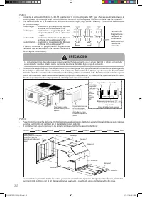
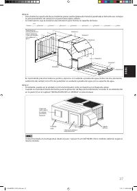
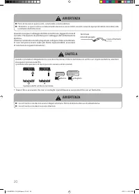
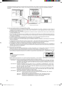
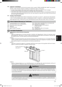
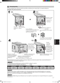
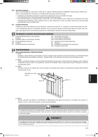
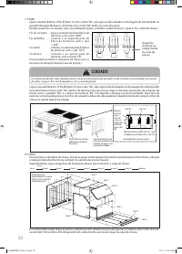
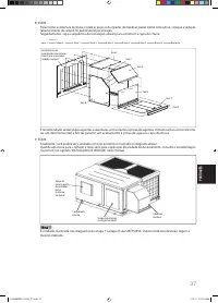
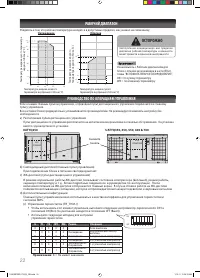
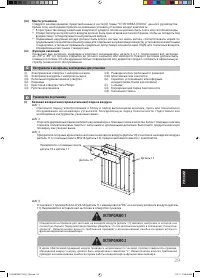
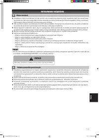
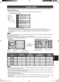
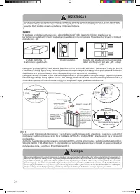
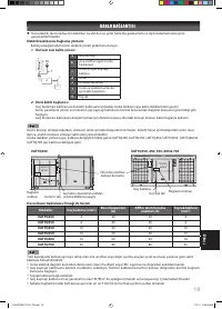
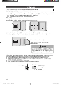
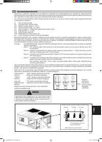
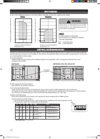
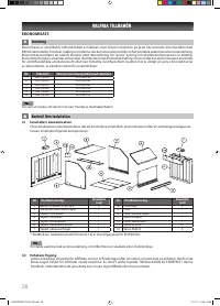
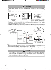
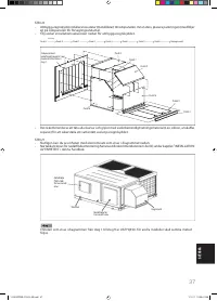
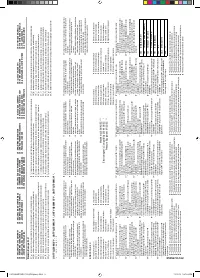
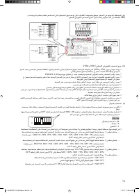
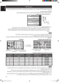
(iv) Auxilliary Electrical Heater Output (HTR1 and HTR2)
There are two output pins (HTR1 and HTR2) on controller main board, which are used to energize the heater
contactor. The contactor must be selected accordingly to avoid any safety issue(s).
The heater shall be installed in accordance with local and national legislation. It must comply with EN60335-2-40.
Thermal fuse(s) shall be installed on the heater to eliminate any danger or damage on the heater/unit. This is
especially critical when there is any malfunction happen to controller main board or blower.
The heater shall be in a safe location, whereby no risk of damage could be happen on the unit.
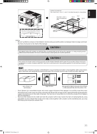
Use non-fl ammable duct for the unit that is installed with heater
Use diff erent power supply for electrical heater and install a circuit breaker for each of the heater.
Maximum temperature in the unit must not exceed 60°C. Temperature measurement shall be taken during the
installation or commisioning in order to ensure the temperature not exceed this value.
Select the proper safety device or thermal protector accordingly.
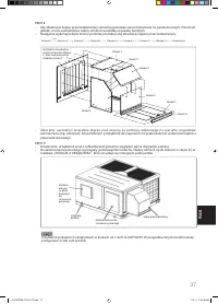
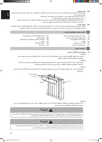
The heater shall never be installed inside the unit. The recommended location for the heater is inside the supply
duct, whereby the distance of the heater is suffi
cient to ensure the temperature inside the unit does not exceed
60°C.
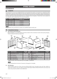
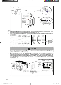
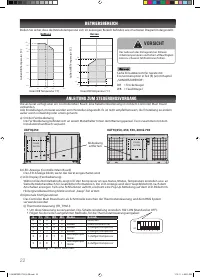
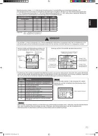
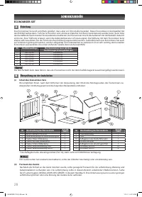
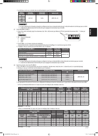
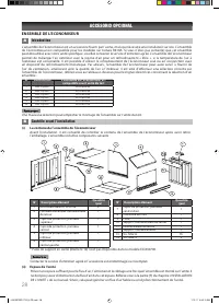
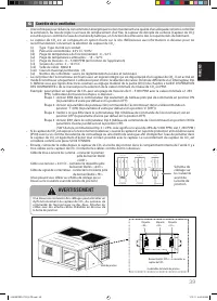
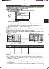
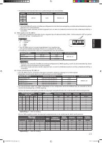
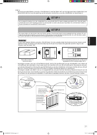
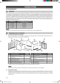
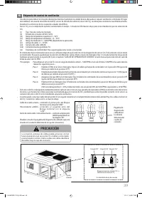
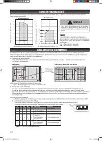
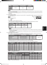
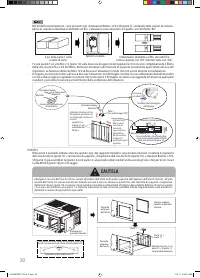
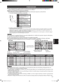
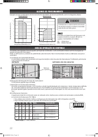
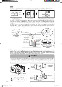
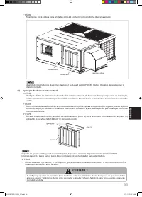
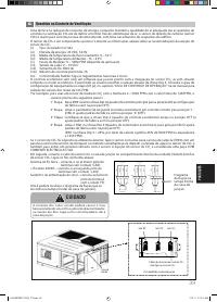
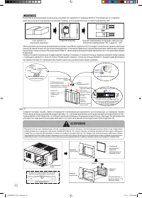
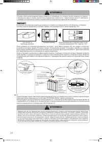
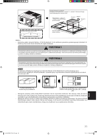
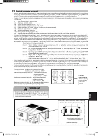
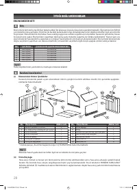
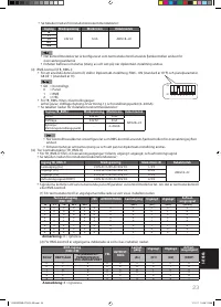
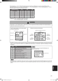
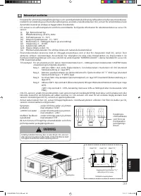
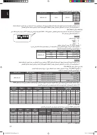
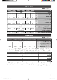
(v) Economizer control
Ensure the economizer kit has been incorporated with rooftop unit before activate the economizer function in
the controller main board. Else, error will occur.
To activate economizer function, set Dip Switch Setting: SW4 - ON (default is OFF) in the controller main board
and panel parameter G6 to ‘1’ (default is ‘0’).
G6 = Economizer control
0 = disable
1 = enable.
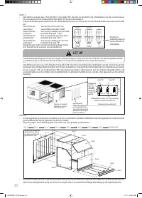
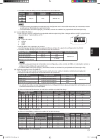
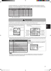
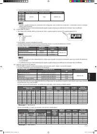
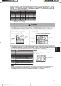
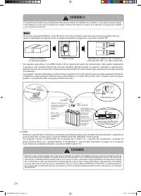
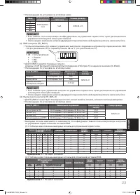
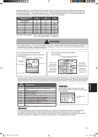
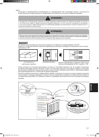
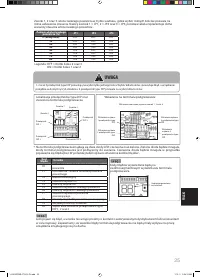
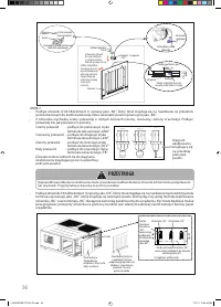
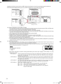
In economizer controller board, there are 4 dip switches and 3 shunt jumpers which provide fl exible selection
based on diff erent requirements:
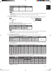
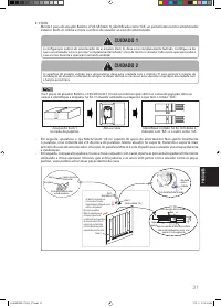
– Dip Switch 1: Minimum fresh air opening setting in heating mode, where by the selection of diff erent pins will
give diff erent opening setting. SW1: 5%, SW2: 10%, SW3: 15%, SW4: 20%, SW5: 25%, SW6/7/8:
no function, Default: 0% (no selection, all OFF).
– Dip Switch 2: Minimum fresh air opening setting in cooling mode, where by the selection of diff erent pins will
give diff erent opening setting. SW1: 0%, SW2: 5%, SW3: 15%, SW4: 20%, SW5: 25%, SW6/7/8:
no function, Default: 10% (no selection, all OFF).
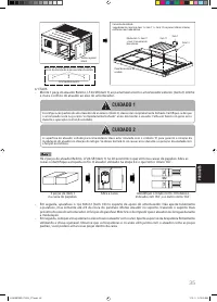
– Dip Switch 3: CO
2
PPM level threshold value selection, where by the selection of diff erent pins will give
diff erent value setting. SW1: 25%, SW2: 50%, SW3: 75%, SW4: 100%, Default: 0% (no selection,
all OFF).
– Dip Switch 4: Type of operation, which include the following selection:-
SW1: OFF = Diff erential temperature operation (default), ON = No function at this moment.
SW2: OFF = Economizer mode (default), ON = Fresh air mode.
SW3: OFF = Overcooled protection is activated (default), ON = Overcooled protection is not
activated.
ü
ü
ü
ü
ü
ü
ü
ü
ü
ü
ü
ü
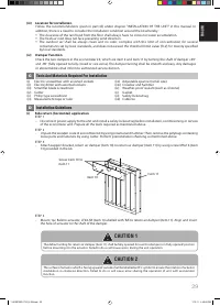
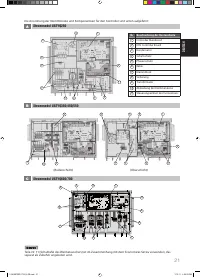
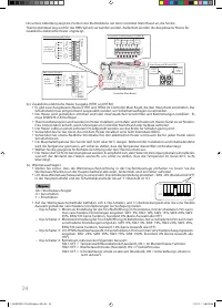
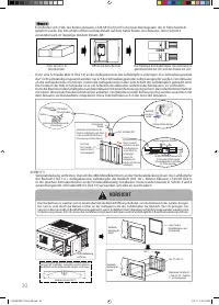
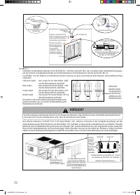
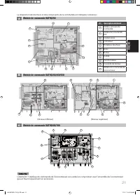
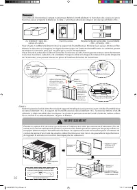
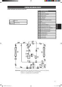
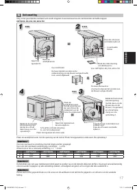
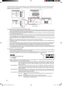
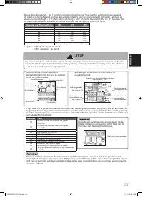
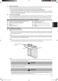
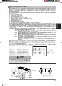
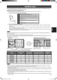
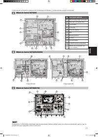
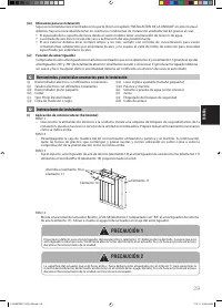
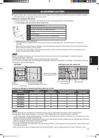
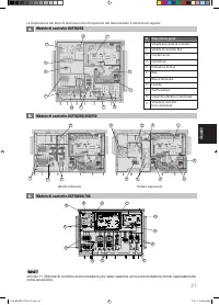
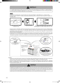
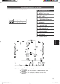
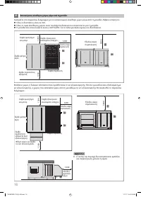
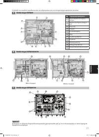
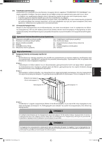
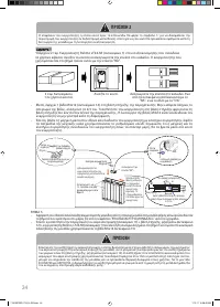
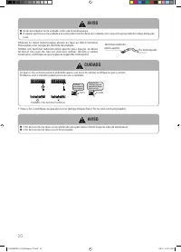
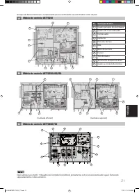
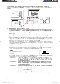
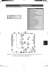
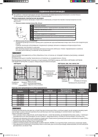
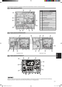
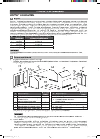
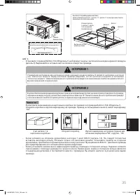
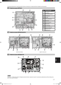
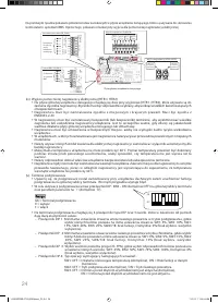
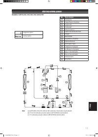
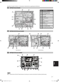
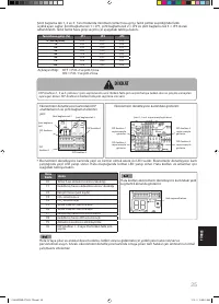
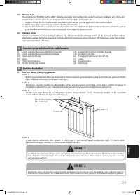
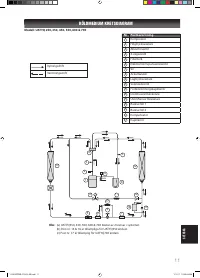
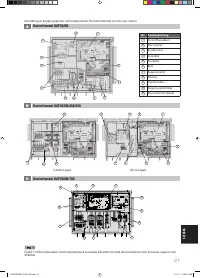
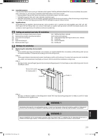
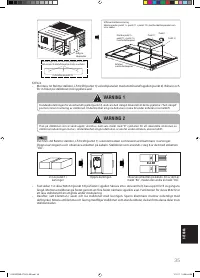
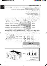
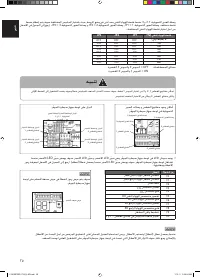
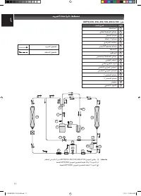
The diagram below shows the position for terminal blocks in the controller main board which are used for
thermostat control and BMS system. Beside that, the output pins for auxilliary electrical heater are shown as well.
1
2
3
4 5
8
6 7
ON
OFF
1 IM 5RTBR-0710(4)DK(denv)-EN.in24 24
1 IM 5RTBR-0710(4)DK(denv)-EN.in24 24
10/15/12 9:04:20 AM
10/15/12 9:04:20 AM


