Кондиционеры Daikin UATYQ-CY1 - инструкция пользователя по применению, эксплуатации и установке на русском языке. Мы надеемся, она поможет вам решить возникшие у вас вопросы при эксплуатации техники.
Если остались вопросы, задайте их в комментариях после инструкции.
"Загружаем инструкцию", означает, что нужно подождать пока файл загрузится и можно будет его читать онлайн. Некоторые инструкции очень большие и время их появления зависит от вашей скорости интернета.


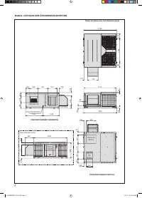


36
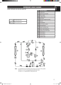
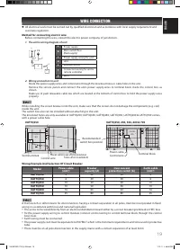
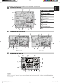
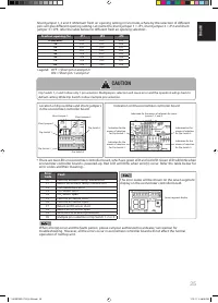
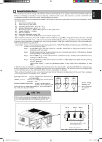
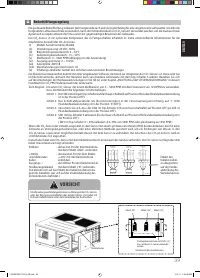
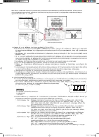
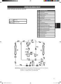
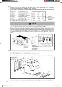
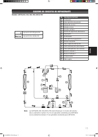
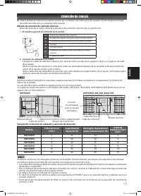
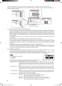
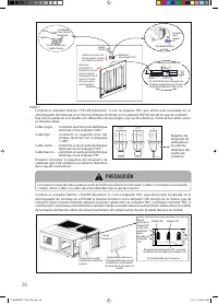
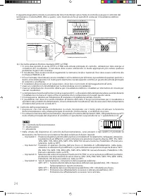
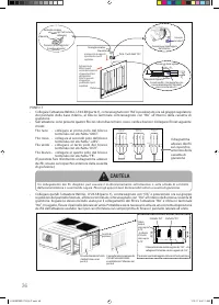
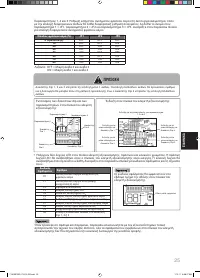
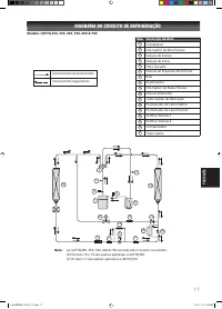
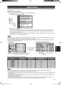
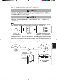
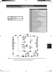
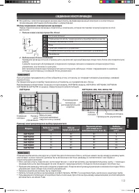
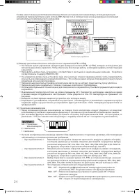
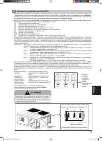
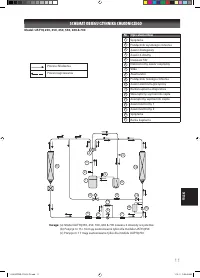
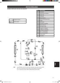
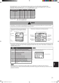
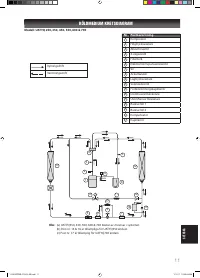
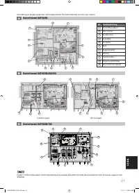
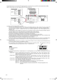
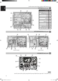
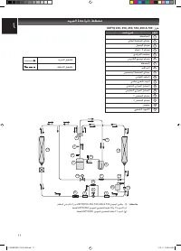
TO PCB3 (ECO)
CN_ACT_RA
TO PCB3 (ECO)
CN_ACT_OA
TO PCB3 (ECO)
CN_C02
TB RA
TB OA
TB C02
BLA
CK
RED
GREEN
WHITE
BLA
CK
RED
GREEN
WHITE
BLA
CK
RED
WHITE
GND +24V DCV
FB
GND +24V DCV
FB
GND +24V
FB
ACTUATOR RA
ACTUATOR OA
C02 SENSOR
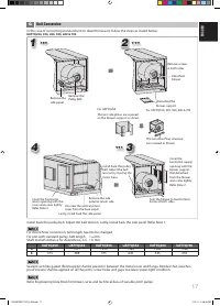
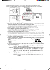
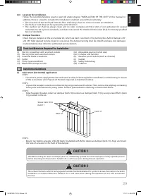
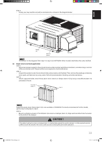
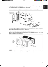
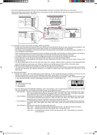
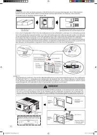
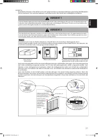
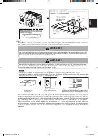
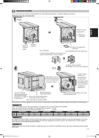
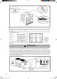
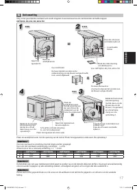
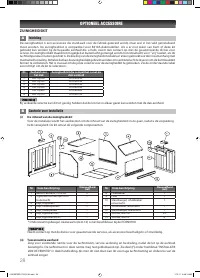
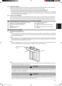
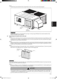
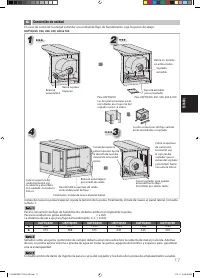
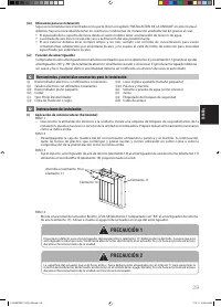
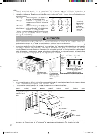
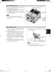
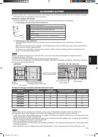
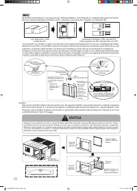
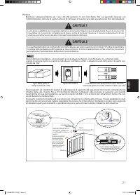
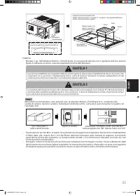
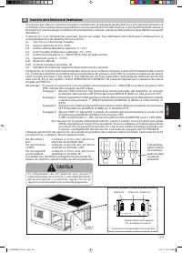
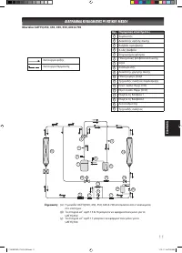
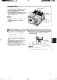
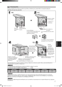
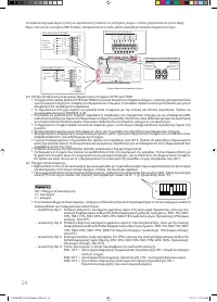
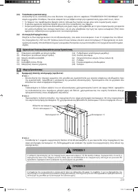
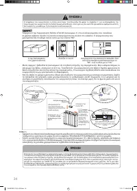
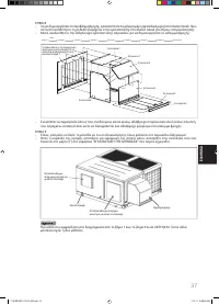
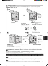
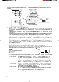
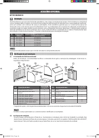
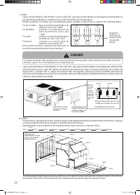
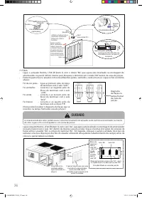
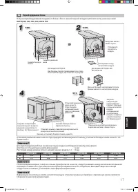
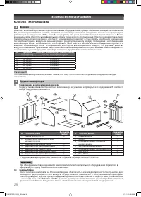
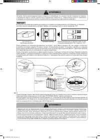
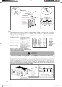
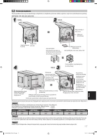
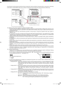
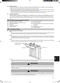
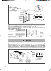
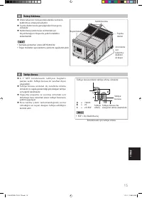
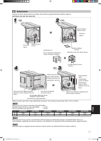
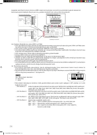
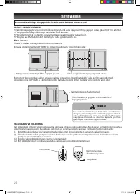
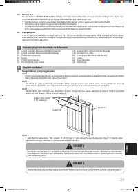
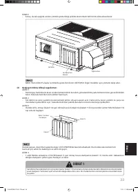
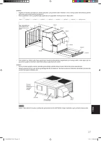
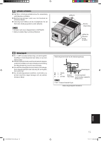
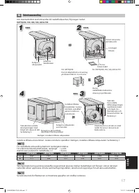
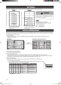
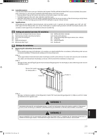
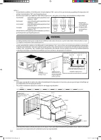
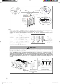
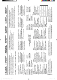
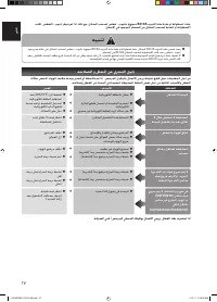
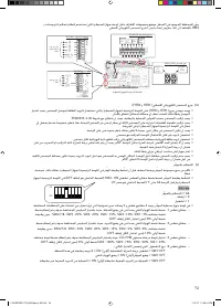
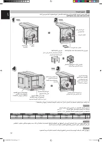
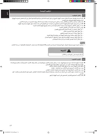
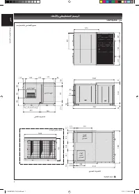
STEP 7
-
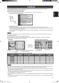
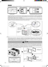
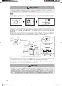
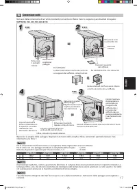
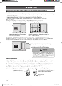
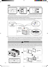
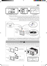
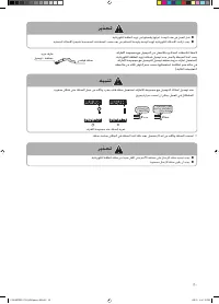
Connect Belimo actuator, LF24-SR (item 1) with label ‘RA’, which is now located at the assembly damper on the
indoor base panel to terminal block with label ‘RA’ inside the junction box.
-
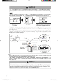
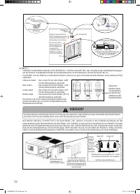
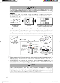
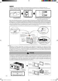
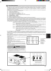
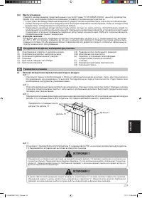
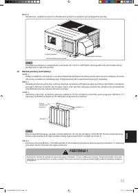
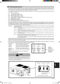
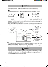
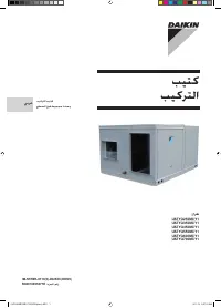
There are four wires on the actuator with diff erent colours (black, red, green and white colours). Connect the
wires as below:
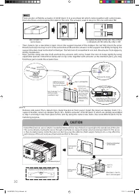
Black colour wire - connect to fi rst pole of
terminal block with label ‘GND’.
Red colour wire
- connect to second pole of
terminal block with label
‘+24V’.
Green colour wire - connect to third pole of
terminal block with label ‘DCV’.
White colour wire - connect to fourth pole of
terminal block with label ‘FB’.
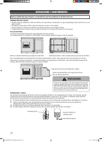
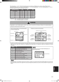
(You may refer to sticker wiring diagram which is
located on the front cover of junction box.)
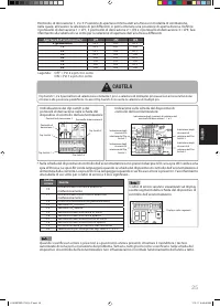
Sticker wiring
diagram on
the front cover
of junction
box
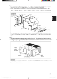
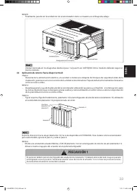
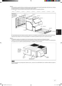
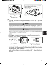
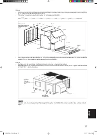
-
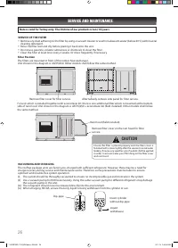
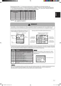
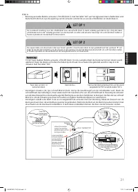
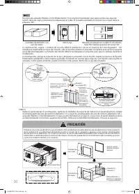
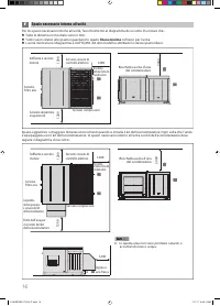
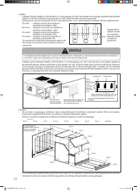
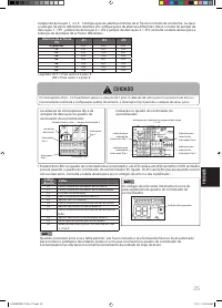
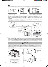
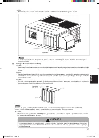
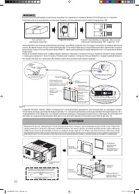
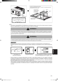
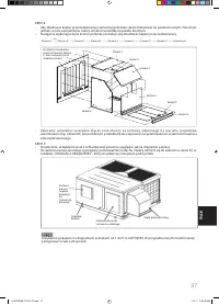
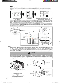
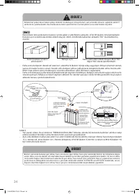
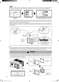
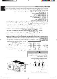
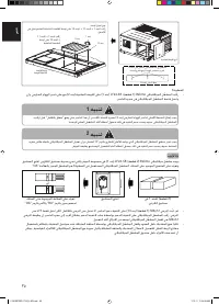
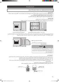
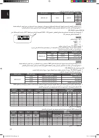
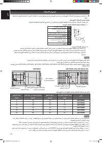
Then, connect Belimo actuator, LF24-SR (item 1) with label ‘OA’, which is now located at the assembly damper
on the side panel to terminal block with label ‘OA’ inside the same junction box. Follow the same method used
for wiring connection between actuator ‘RA’ and terminal block ‘RA’. Next, attach the side panel to the unit. You
may need to do proper arrangement on the actuator wires by using cable ties (fi eld supply) before attach the
side panel to the unit.
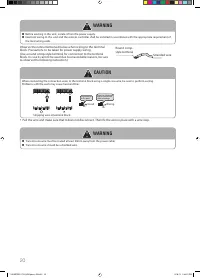
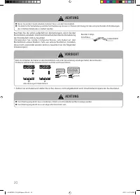
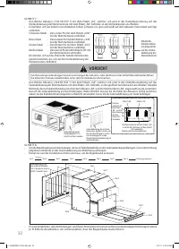
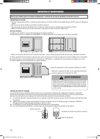
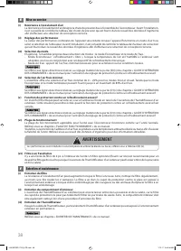
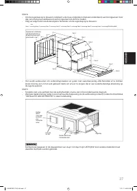
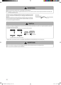
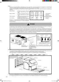
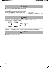
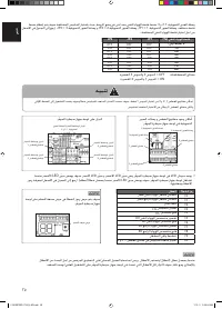
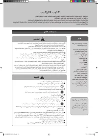
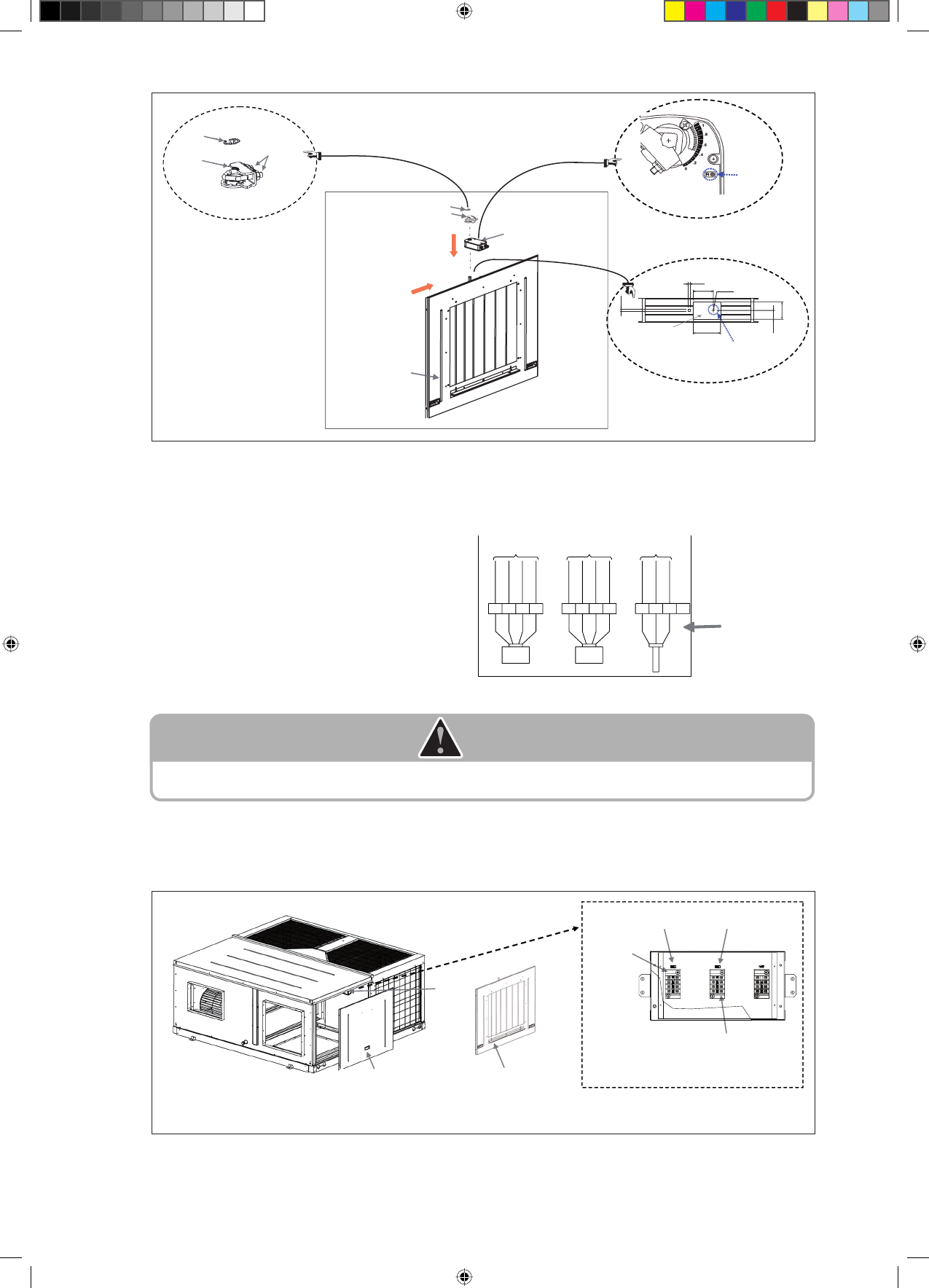
CAUTION
Wrong wiring connection may cause the malfunction on actuator or economizer controller board or both. Tie the wires
with releasable cable ties under the junction box.
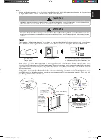
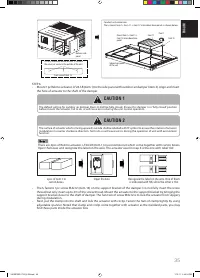
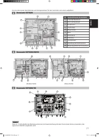
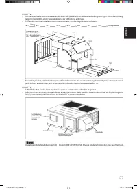
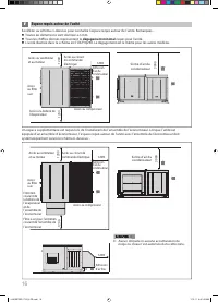
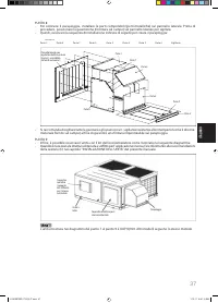
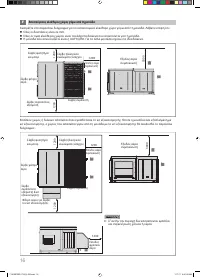
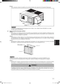
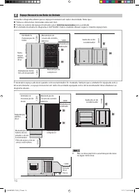
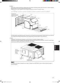
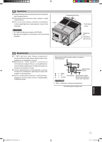
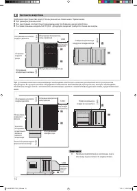
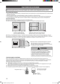
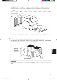
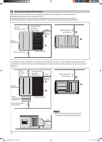
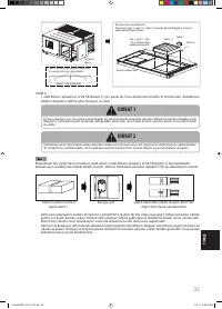
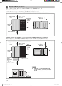
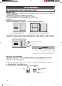
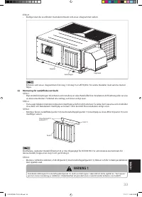
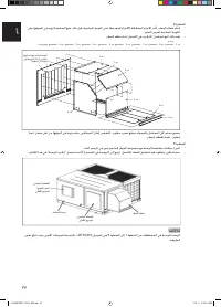
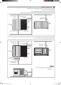
Side panel in standard
unit which is removed in
step 5.
Junction
box
Side panel comes with
economizer kit box which is
assembled with actuator in
step 6. Attach this panel to
the unit.
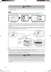
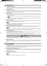
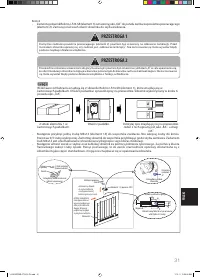
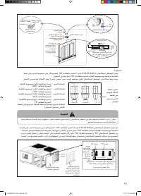
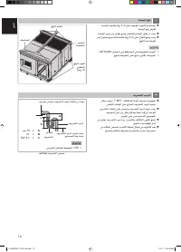
Terminal
block with
label ‘RA’
- to be
connected
with actuator
with label
‘RA’
Label ‘RA’
Label ‘OA’
Terminal block with label ‘OA’ - to be
connected with actuator with label ‘OA’.
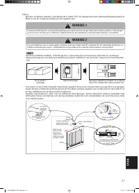
Detail view of junction box
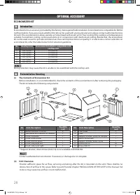
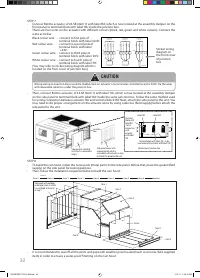
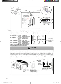
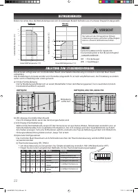
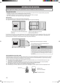
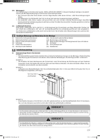
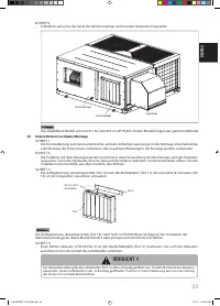
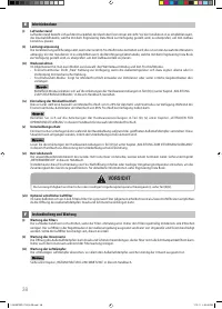
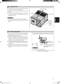
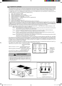
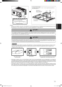
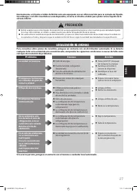
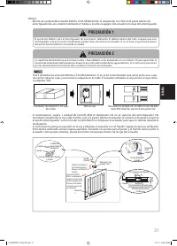
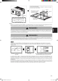
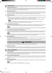
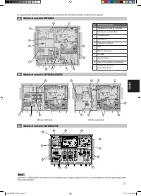
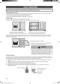
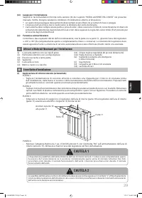
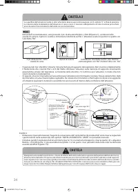
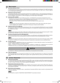
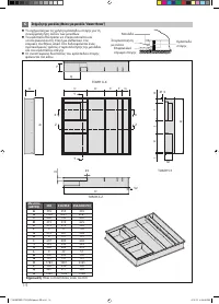
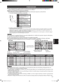
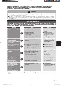
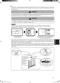
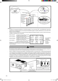
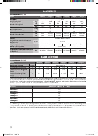
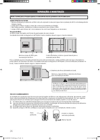
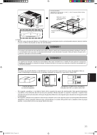
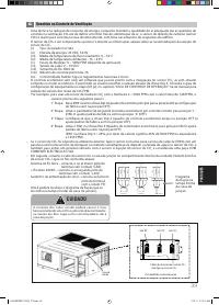
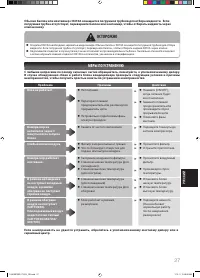
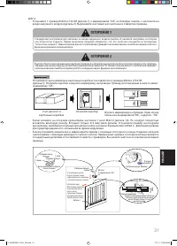
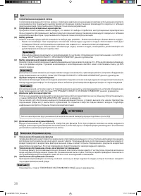
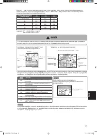
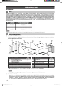
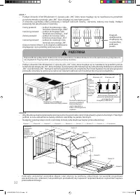
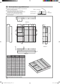
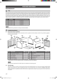
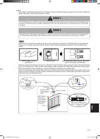
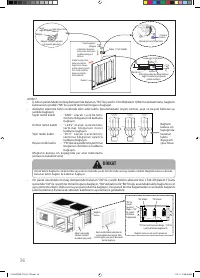
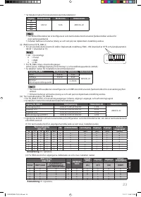
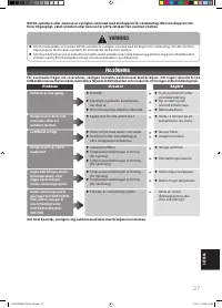
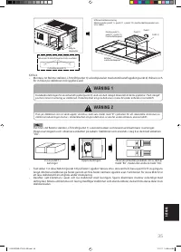
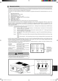
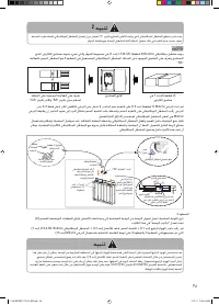
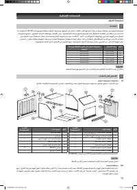
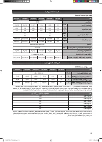
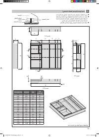
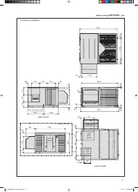
Circlip
Clamp
Item 1 (with label ‘OA’)
Item 2
Circlip
Clamp
2pcs of Nuts
(screw tightly)
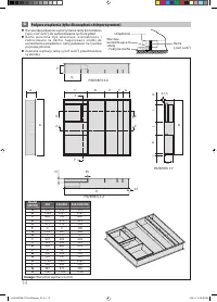
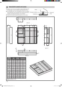
Details view for clamp
and circlip
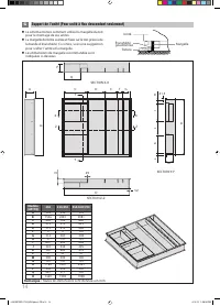
Support bracket
Fasten M4x16 screw on this hole, do
not fully insert the screw thread, but
insert only 2/3 of the thread.
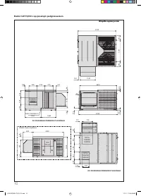
Top view for damper
Labelled
with ‘R’
symbol
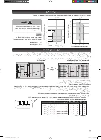
Detail view for actuator
12
12
110
Ø3
150
45
90
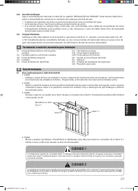
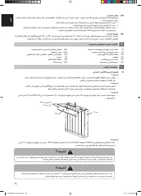
a) Mount the actuator
to the shaft of damper,
then lock with circlip and
clamp.
b) Insert screw
M4x12, then bring
the support bracket
closer to the shaft
of damper. Note:
support bracket is
located on the top of
damper.
1 IM 5RTBR-0710(2)-EN.indd 36
1 IM 5RTBR-0710(2)-EN.indd 36
1/10/11 3:39:31 PM
1/10/11 3:39:31 PM


