Электропилы Bosch PPS 7 S - инструкция пользователя по применению, эксплуатации и установке на русском языке. Мы надеемся, она поможет вам решить возникшие у вас вопросы при эксплуатации техники.
Если остались вопросы, задайте их в комментариях после инструкции.
"Загружаем инструкцию", означает, что нужно подождать пока файл загрузится и можно будет его читать онлайн. Некоторые инструкции очень большие и время их появления зависит от вашей скорости интернета.


48
| English
1 609 929 W71 | (30.3.11)
Bosch Power Tools
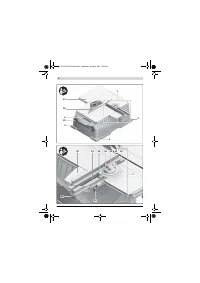
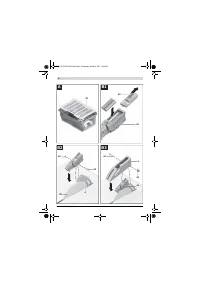
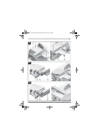
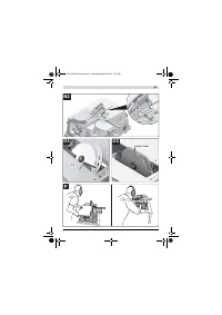
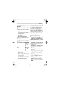
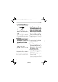
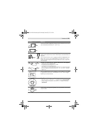
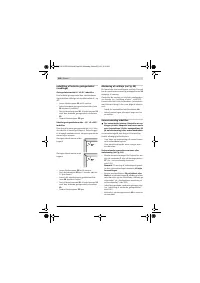
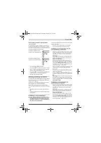
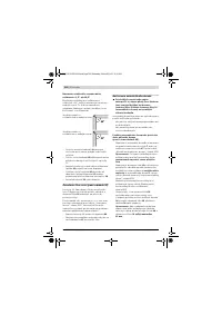
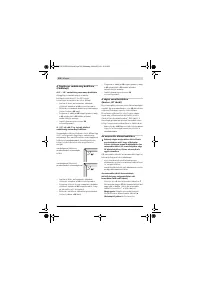
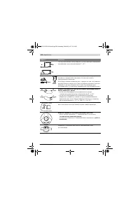
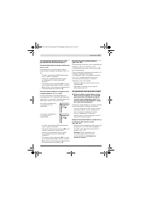
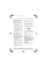
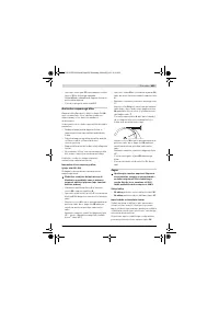
Using the Universal Guide as a Parallel Guide
(see figure N2)
– Mount the universal guide
1
left or right on
the saw table
7
or the table extension
27
.
(see “Mounting the Universal Guide”,
page 44)
Note:
When sawing bevel angles, the univer-
sal guide should be mounted to the
right of
the saw blade
.
– Depending on the workpiece size and on the
set bevel angle, mount the fence
36
upright
or flat
to the universal guide
1
. (see “Mount-
ing the Fence to the Universal Guide”,
page 44)
Note:
When sawing, workpieces can become
jammed between the universal guide and the
saw blade, be caught by the rotating saw
blade, and be thrown from the machine.
Therefore, adjust the fence
36
in such a man-
ner that its guiding end ends in the area be-
tween the saw blade centre and the riving
knife.
For this, loosen wing bolt
34
, move the fence
and retighten the wing bolt again.
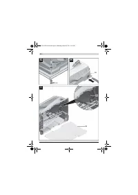
– Adjust a 0 ° mitre angle. (see “Adjusting Mitre
Angles”, page 46)
– Loosen wing bolt
37
and move the guide rail
31
to the desired clearance.
The scale
14
indicates the clearance be-
tween saw blade and fence.
– Tighten wing bolt
37
again.
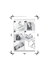
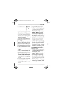
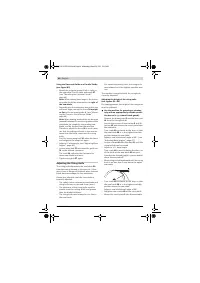
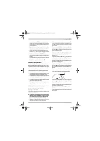
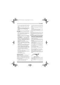
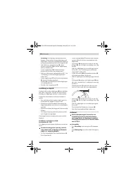
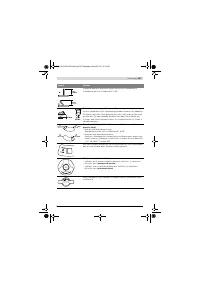
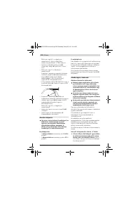
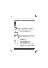
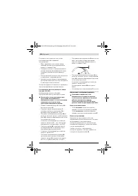
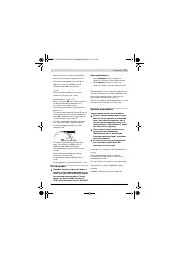
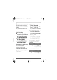
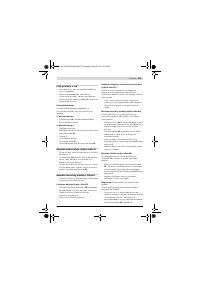
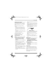
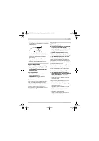
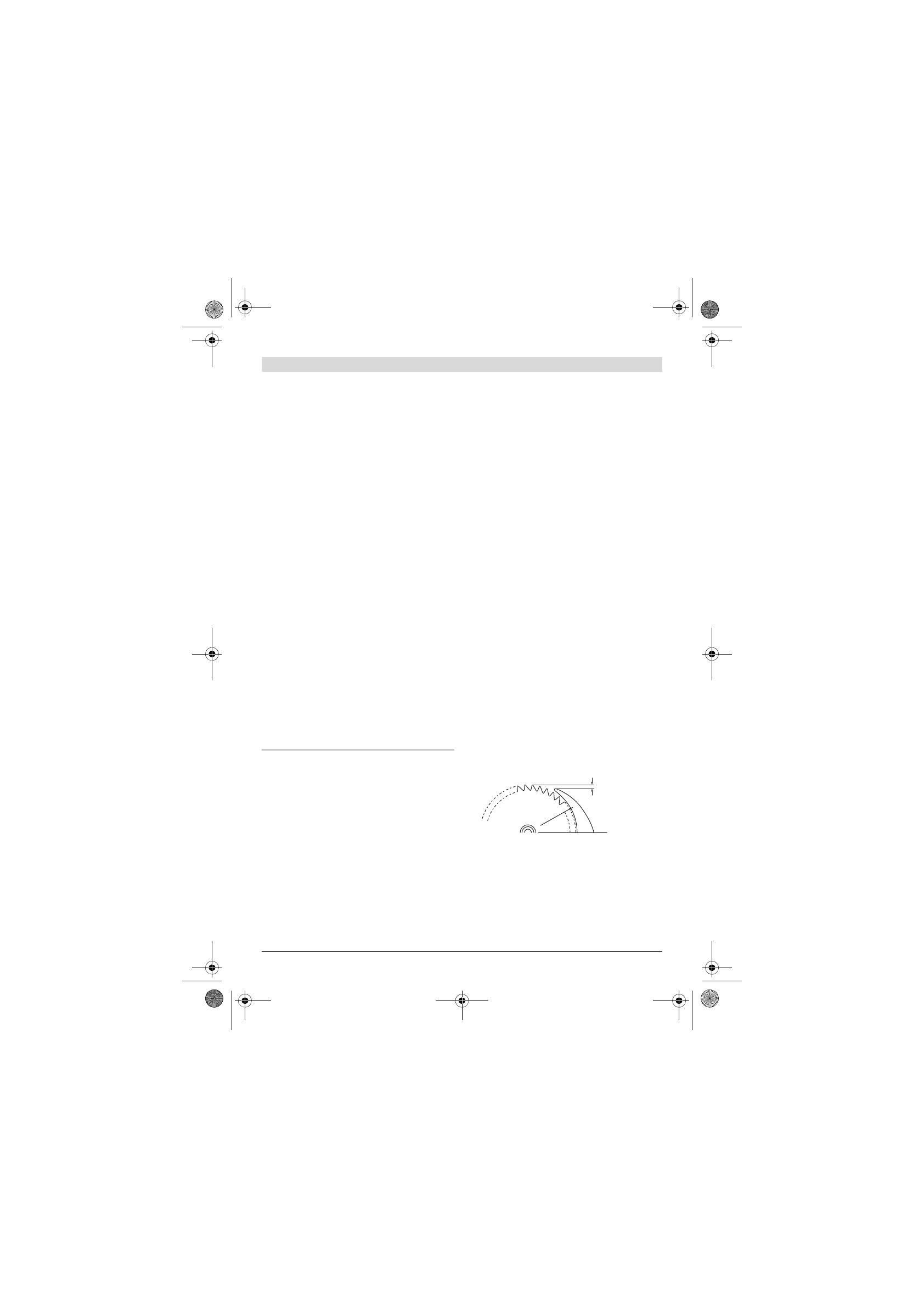
Adjusting the Riving Knife
The riving knife
4
prevents the saw blade
28
from becoming jammed in the saw cut. Other-
wise, there is danger of kickback when the saw
blade becomes wedged in the workpiece.
Always pay attention that the riving knife is
properly adjusted:
– The radial clearance between saw blade and
riving knife may not exceed 5 mm (max.).
– The thickness of the riving knife must be
smaller than the cutting width and greater
than the blade thickness.
– The riving knife must always be in a line to
the saw blade.
– For normal separating cuts, the riving knife
must always be in the highest possible posi-
tion.
The machine is supplied with the riving knife
correctly adjusted.
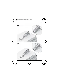
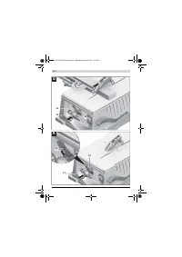
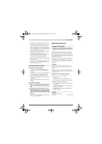
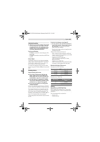
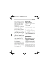
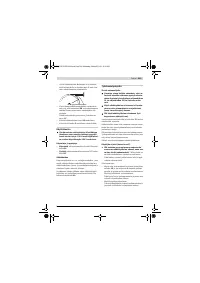
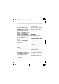
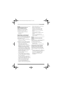
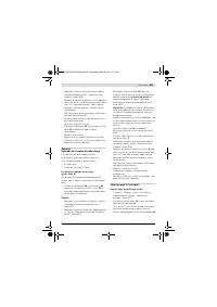
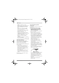
Adjusting the height of the riving knife
(see figures O1 – O2)
For sawing grooves, the height of the riving knife
must be adjusted.
f
Use the machine for grooving or rebating
only with an appropriately suitable protec-
tive device (e. g. a tunnel blade guard).
– Remove the blade guard
3
and the laser unit
41
from the riving knife
4
.
– Loosen the screws of insert plate
5
with Al-
len key
13
and remove the insert plate from
the saw table.
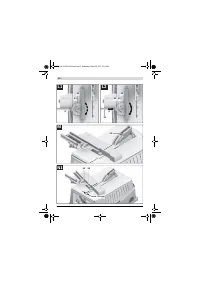
– Turn crank
18
clockwise to the stop, so that
the saw blade
28
is in the highest possible
position above the saw table.
Adjust a saw blade bevel angle of 45 ° . (see
“Adjusting Bevel Angles”, page 47)
– Loosen screws
60
with Allen key
13
, until the
riving knife
4
can be moved.
– Adjust to a 0 ° bevel angle.
Turn crank
18
in anticlockwise direction, un-
til the teeth of the saw blade
28
are posi-
tioned at the desired height (= groove depth)
above the saw table
7
.
– Move riving knife
4
downward until the riving
knife is no less than 5 mm below the upper
saw teeth.
– Turn crank
18
clockwise to the stop, so that
the saw blade
28
is in the highest possible
position above the saw table.
Adjust a saw blade bevel angle of 45 ° .
– Retighten the screws
60
of the riving knife.
– Mount the insert plate
5
into the saw table.
5 mm max.
5 mm max.
OBJ_BUCH-1259-002.book Page 48 Wednesday, March 30, 2011 11:02 AM
Содержание
- 345 Всегда распиливайте только одну деталь.
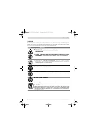
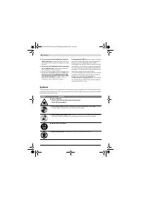
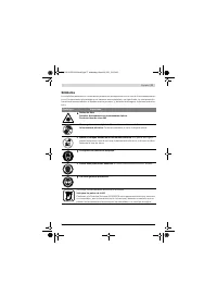
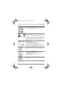
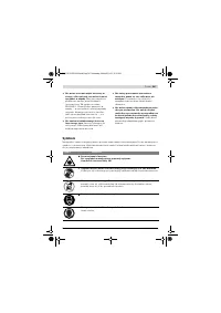
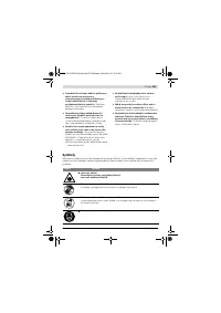
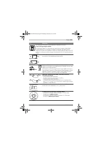
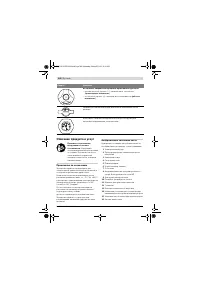
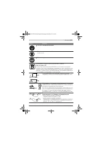
- 346 Символы; Символ
- 347 Русский; Применяйте средства защиты органов слуха.; Воздействие шума может; Используйте защитные очки.; Не выбрасывайте электроинструменты в бытовой мусор!
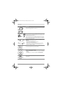
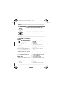
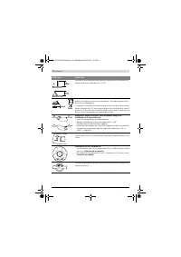
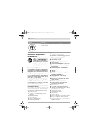
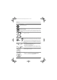
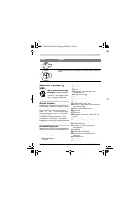
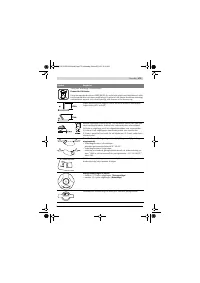
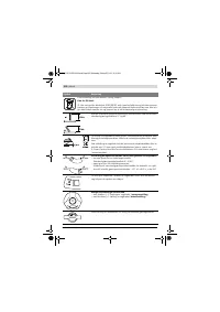
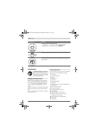
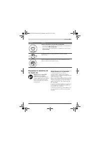
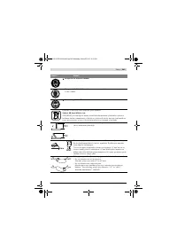
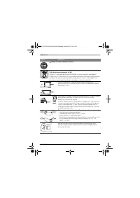
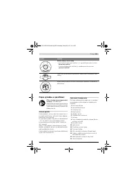
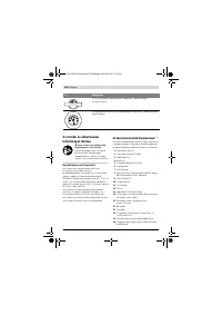
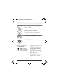
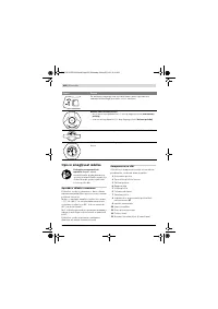
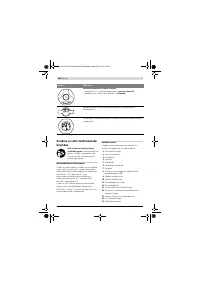
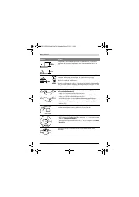
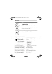
- 348 Описание продукта и услуг; Применение по назначению; Возможные направления вращения кривошипной рукоятки
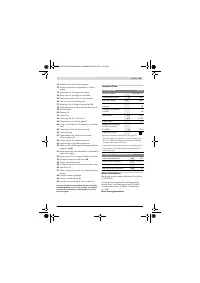
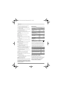
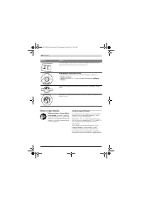
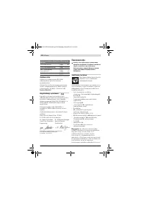
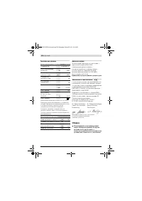
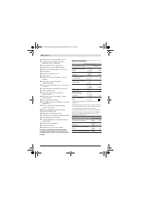
- 350 Технические данные; Применяйте средства защиты органов слуха!; Заявление о соответствии; Сборка; Протяжная циркулярная пила; Размеры пильных дисков
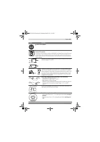
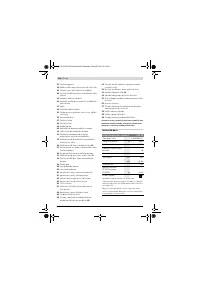
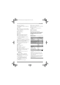
- 351 Комплект поставки; Последовательность монтажа
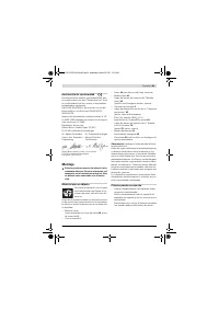
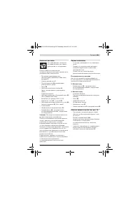
- 352 Монтаж лазера и защитного кожуха; Установка параллельности:
- 353 Настройка ровности; Монтаж удлинителя стола и упоров; справа от пильного
- 354 Отсос пыли и стружки
- 355 Демонтаж пильного диска; Работа с инструментом; Транспортное положение; Увеличение площади стола
- 356 Настройка диапазона угла распила от 0
- 357 Настройка универсального упора
- 358 Включение электроинструмента; включить
- 359 Указания по применению; Общие указания для пиления; Учитывайте при этом следующие указания:; Максимальные размеры заготовки; Этот режим работы пригоден для:; Высота заготовки
- 360 не должно превышать 15 мм
- 361 Хранение и транспортировка; Хранение электроинструмента; Техобслуживание и сервис; Техобслуживание и очистка; Очистка; Принадлежности
- 362 Россия; Утилизация


