Сварочное оборудование Telwin SUPERIOR TIG 422 AC DC HF LIFT - инструкция пользователя по применению, эксплуатации и установке на русском языке. Мы надеемся, она поможет вам решить возникшие у вас вопросы при эксплуатации техники.
Если остались вопросы, задайте их в комментариях после инструкции.
"Загружаем инструкцию", означает, что нужно подождать пока файл загрузится и можно будет его читать онлайн. Некоторые инструкции очень большие и время их появления зависит от вашей скорости интернета.


- 9 -
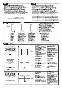
6.1.3 TIG AC welding
This type of welding can be used to weld metals such as aluminium and magnesium,
which form a protective, insulating oxide on their surface. By reversing the welding
current polarity it is possible to “break” the surface layer of oxide by means of a
mechanism called “ionic sandblasting”. The voltage on the tungsten electrode
alternates between positive (EP) and negative (EN). During the EP period the oxide
is removed from the surface (“cleaning”or “pickling”) allowing formation of the pool.
During the EN period there is maximum heat transfer to the piece, allowing welding.
The possibility of varying the balance parameter in AC means that it is possible to
reduce the EP current period to a minimum, allowing quicker welding.
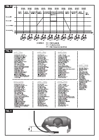
Higher balance values give quicker welding, greater penetration, a more concentrated
arc, a narrower weld pool and limited heating of the electrode. Lower values give a
cleaner piece. If the balance value is too low this will widen the arc and the de-oxidised
part, overheat the electrode with consequent formation of a sphere on the tip making it
more difficult to strike the arc and control its direction. If the balance value is too high
this will create a “dirty” weld pool with dark inclusions.
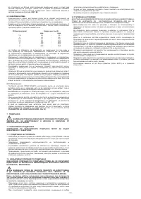
The table
(TAB.
4)
summarises the effects of parameter changes in AC welding.
In TIG AC mode 2-stroke (2T) and 4-stroke (4T) operation are possible.
The instructions for this welding procedure are also valid.
The table
(TAB. 3)
shows suggested values for welding on aluminium; the most
suitable electrode is a pure tungsten electrode (green band).
6.1.4 Procedure
- Use the knob to adjust the welding current to the desired value; if necessary adjust
during welding to the actual required heat transfer.
- Press the torch button and make sure the gas flow from the torch is correct; if
necessary, adjust pre-gas and postgas times; these times should be adjusted
according to operating conditions, the postgas delay in particular should be long
enough to allow the electrode and weld pool to cool at the end of welding without
coming into contact with the atmosphere (oxidation and contamination).
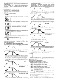
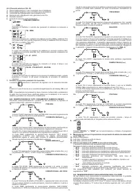
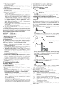
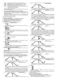
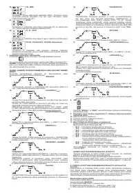
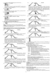
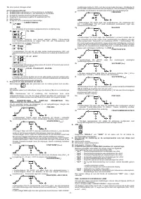
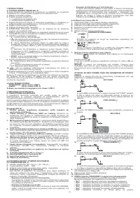
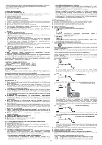
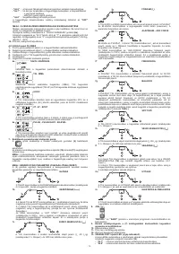
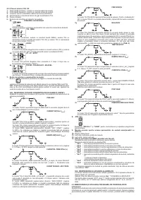
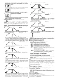
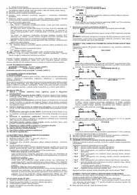
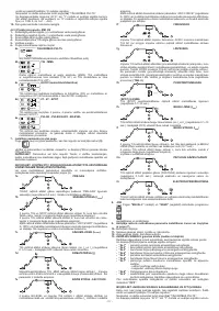
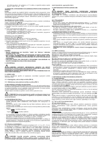
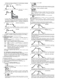
TIG mode with 2T sequence:
- Press the torch button (P.T.) right down to strike the arc with a current of I
START
. The
current will increase according to the START SLOPE UP setting to the welding
current value.
- To interrupt welding, release the torch button so that either the current gradually
decreases (if the FINAL SLOPE DOWN parameter has been enabled) or the arc is
extinguished immediately, followed by postgas.
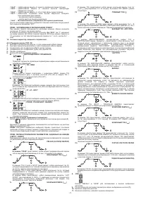
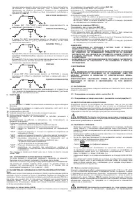
TIG mode with 4T sequence:
- The first time the button is pressed it will strike the arc with a current equal to I
START
.
When the button is released the current will increase according to the START SLOPE
UP setting to the welding current value; this value is maintained even with the button
is released. When the button is pressed again the current will decrease according
to the FINAL SLOPE DOWN setting, until it reaches I
END
. The I
END
current will be
maintained until the button is released to terminate the welding cycle and start the
postgas phase. If, on the other hand, the button is released while the FINAL SLOPE
DOWN function is proceeding, the welding cycle will terminate immediately and the
postgas phase will start.
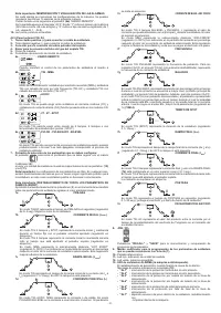
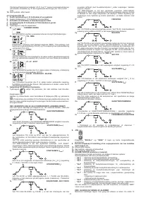
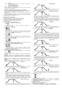
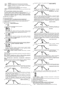
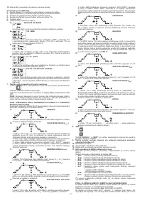
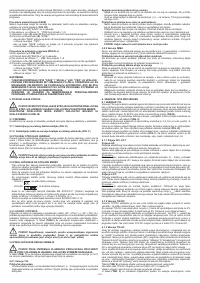
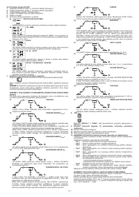
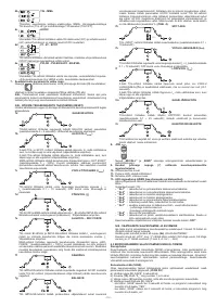
TIG mode with 4T and BI-LEVEL sequence:
- The first time the button is pressed it will strike the arc with a current equal to I
START
.
When the button is released the current will increase according to the START
SLOPE UP setting to the welding current value; this value is maintained even when
the button is released. Now, every time the button is pressed (the time between
pressure and release should be short) the current will change between the setting
for the BI-LEVEL I
1
parameter and the main current value I
2
.
- When the button is kept pressed down for a longer space of time the current will
decrease according to the FINAL SLOPE DOWN setting, until it reaches I
END
. The
I
END
current will be maintained until the button is released to terminate the welding
cycle and start the postgas phase. If, on the other hand, the button is released while
the FINAL SLOPE DOWN function is proceeding, the welding cycle will terminate
immediately and the postgas phase will start (
FIG.M
).
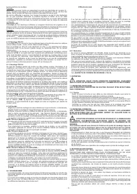
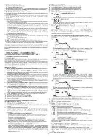
6.2 MMA WELDING
- It is most important that the user refers to the maker’s instructions indicated on the
stick electrode packaging. This will indicate the correct polarity of the stick electrode
and the most suitable current.
- The welding current must be regulated according to the diameter of the electrode in
use and the type of the joint to be carried out: see below the currents corresponding
to various electrode diameters:
Ø Electrode (mm)
Welding current (A)
min.
max.
1.6
25
-
50
2
40
-
80
2.5
60
-
110
3.2
80
-
160
4
120
-
200
5
150
-
280
6
200
-
350
- The user must consider that, according to the electrode diameter, higher current
values must be used for flat welding, whereas for vertical or overhead welds lower
current values are necessary.
- As well as being determined by the chosen current intensity, the mechanical
characteristics of the welded join are also determined by the other welding parameters
i.e. arc length, working rate and position, electrode diameter and quality (to store
the electrodes correctly, keep them in a dry place protected by their packaging or
containers).
- The properties of the weld also depend on the ARC-FORCE value (dynamic
behaviour) of the welding machine. The setting for this parameter can be made
either on the panel or using the remote control with 2 potentiometers.
- It should be noted that high ARC-FORCE values achieve better penetration and
allow welding in any position typically with basic electrodes, low ARC-FORCE values
give a softer, spray-free arc typically with rutile electrodes.
The welding machine is also equipped with HOT START and ANTI STICK devices to
guarantee easy starts and to prevent the electrode from sticking to the piece.
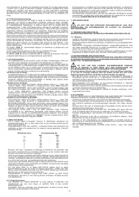
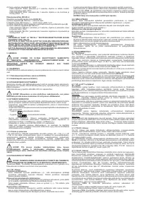
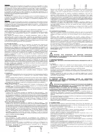
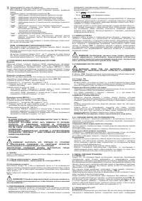
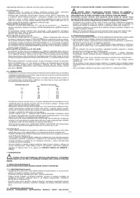
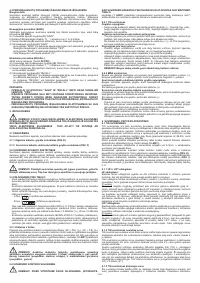
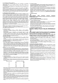
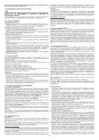
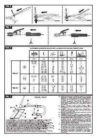
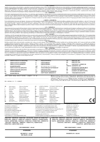
6.2.1 Procedure
- Holding the mask IN FRONT OF THE FACE, strike the electrode tip on the workpiece
as if you were striking a match. This is the correct strike-up method.
WARNING:
do not hit the electrode on the workpiece, this could damage the
electrode and make strike-up difficult.
- As soon as arc is ignited, try to maintain a distance from the workpiece equal to the
diameter of the electrode in use. Keep this distance as much constant as possible
for the duration of the weld. Remember that the angle of the electrode as it advances
should be of 20-30 grades.
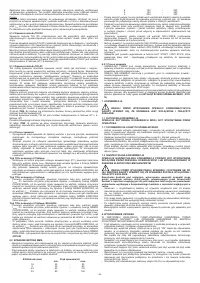
- At the end of the weld bead, bring the end of the electrode backward, in order to
fill the weld crater, quickly lift the electrode from the weld pool to extinguish the arc
(CHARACTERISTICS OF THE WELD BEAD - FIG. N)
.
7. MAINTENANCE
WARNING! BEFORE CARRYING OUT MAINTENANCE OPERATIONS
MAKE SURE THE WELDING MACHINE IS SWITCHED OFF AND DISCONNECTED
FROM THE MAIN POWER SUPPLY.
7.1 ROUTINE MAINTENANCE
ROUTINE MAINTENANCE OPERATIONS CAN BE CARRIED OUT BY THE
OPERATOR.
7.1.1 Torch
- Do not put the torch or its cable on hot pieces; this would cause the insulating
materials to melt, making the torch unusable after a very short time.
- Make regular checks on the gas pipe and connector seals.
- Accurately match collet and collet body with the selected electrode diameter in order
to avoid overheating, bad gas diffusion and poor performance.
- At least once a day check the terminal parts of the torch for wear and make sure they
are assembled correctly: nozzle, electrode, electrode-holder clamp, gas diffuser.
7.2 EXTRAORDINARY MAINTENANCE
EXTRAORDINARY MAINTENANCE OPERATIONS SHOULD BE CARRIED
OUT ONLY AND EXCLUSIVELY BY SKILLED OR AUTHORISED ELECTRICAL-
MECHANICAL TECHNICIANS.
WARNING! BEFORE REMOVING THE WELDING MACHINE PANELS
AND WORKING INSIDE THE MACHINE MAKE SURE THE WELDING MACHINE
IS SWITCHED OFF AND DISCONNECTED FROM THE MAIN POWER SUPPLY
OUTLET.
If checks are made inside the welding machine while it is live, this may cause
serious electric shock due to direct contact with live parts and/or injury due to
direct contact with moving parts.
- Periodically, and in any case with a frequency in keeping with the utilisation and with
the environment’s dust conditions, inspect the inside of the welding machine and
remove the dust deposited on the electronic boards with a very soft brush or with
appropriate solvents.
- At the same time make sure the electrical connections are tight and check the wiring
for damage to the insulation.
- At the end of these operations re-assemble the panels of the welding machine and
screw the fastening screws right down.
- Never, ever carry out welding operations while the welding machine is open.
8. TROUBLESHOOTING
IN CASE OF UNSATISFACTORY FUNCTIONING, BEFORE SERVICING MACHINE
OR REQUESTING ASSISTANCE, CARRY OUT THE FOLLOWING CHECK:
- Check that the welding current is correct for the diamter and electrode type in use.
- Check that when general switch is ON the relative lamp is ON. If this is not the case
then the problem is located on the mains (cables, plugs, outlets, fuses, etc.).
- Check that the yellow led (ie. thermal protection interruption- either over or
undervoltage or short circuit) is not lit.
- Check that the nominal intermittance ratio is correct. In case there is a thermal
protection interruption, wait for the machine to cool down, check that the fan is
working properly.
- Check the mains voltage: if the value is too high or too low the welding machine will
be stopped.
- Check that there is no short-circuit at the output of the machine: if this is the case
eliminate the incovenience.
- Check that all connections of the welding circuit are correct, particularly that the
work clamp is well attached to the workpiece, with no interferring material or surface-
coverings (ie. Paint).
- Protective gas must be of appropriate type (Argon 99,5%) and quantity.


