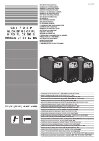
Сварочное оборудование Telwin SUPERIOR TIG 422 AC DC HF LIFT - инструкция пользователя по применению, эксплуатации и установке на русском языке. Мы надеемся, она поможет вам решить возникшие у вас вопросы при эксплуатации техники.
Если остались вопросы, задайте их в комментариях после инструкции.
"Загружаем инструкцию", означает, что нужно подождать пока файл загрузится и можно будет его читать онлайн. Некоторые инструкции очень большие и время их появления зависит от вашей скорости интернета.


- 7 -
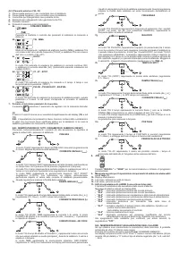
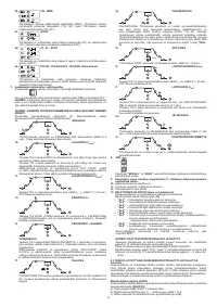
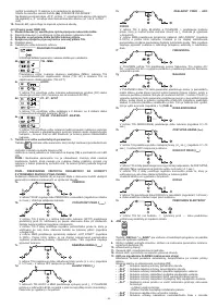
N.B.: ALARMS STORAGE AND DISPLAY
With every alarm the machine’s setting are stored. It is possible to recall the last
10 alarms as follows:
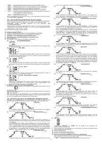
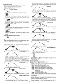
Press pushbutton
(6a)
“REMOTE COMMAND” for a few seconds
Code “AY.X” is displayed, where “Y” indicates the alarm number (A0 most recent,
A9 oldest) and “X” indicates the type of alarm recorded (from 1 to 8, see AL1 ...
AL8).
12-
Green led, power on.
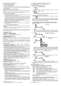
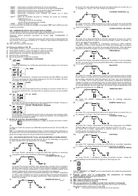
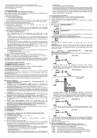
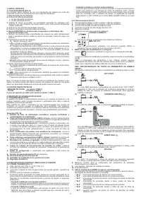
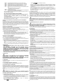
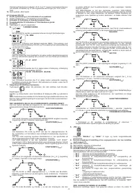
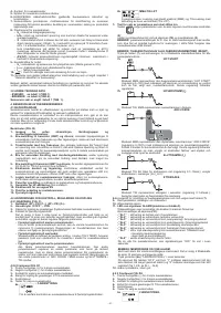
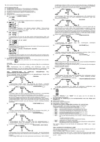
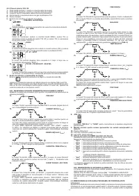
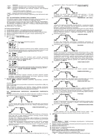
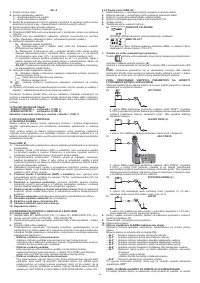
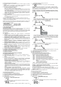
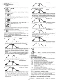
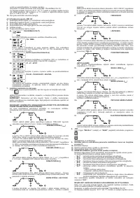
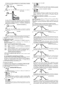
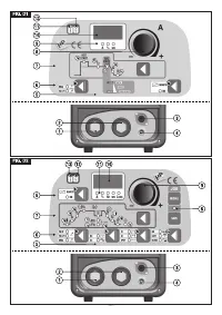
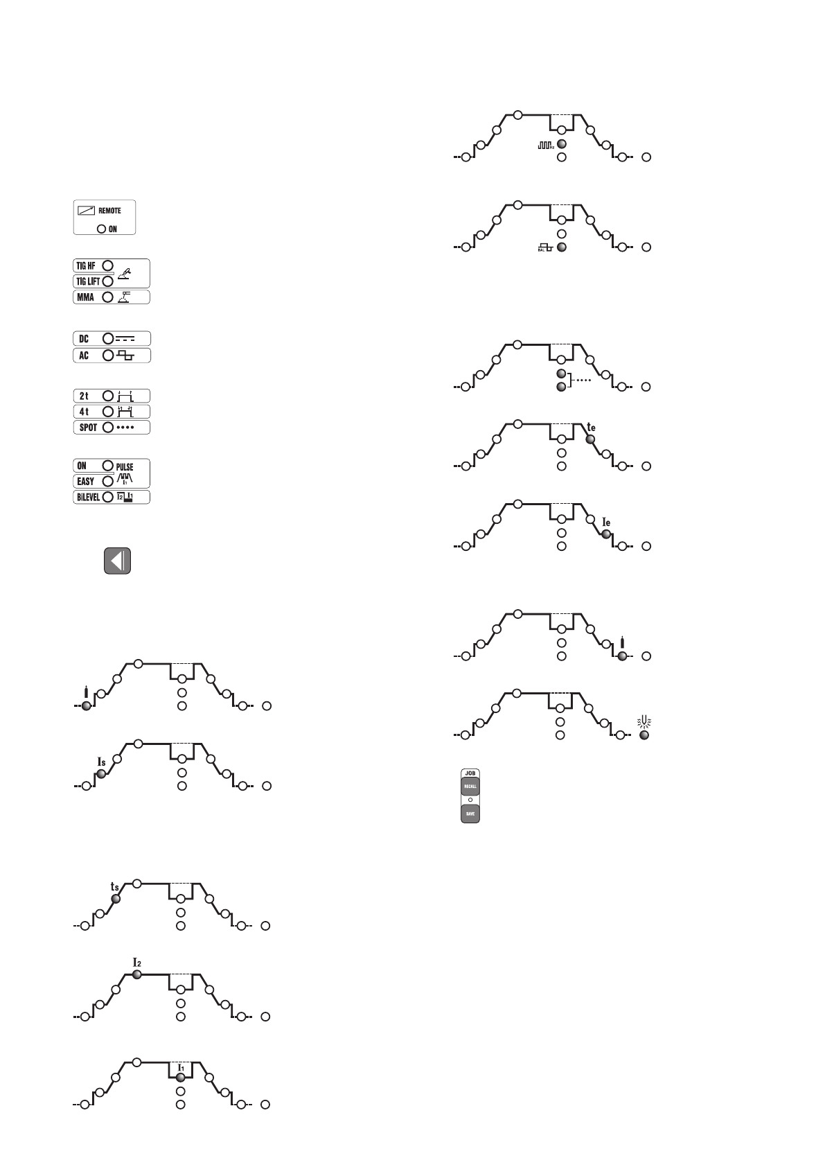
4.2.3 Front panel FIG. D2
1-
Positive quick latch (+) to connect the welding cable.
2-
Negative quick latch (-) to connect the welding cable.
3-
Connector for connecting the torch pushbutton cable.
4-
Fitting for connecting the gas pipe of the TIG torch.
5-
Controls panel.
6-
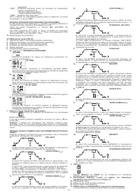
Welding modes selection pushbuttons:
6a
REMOTE COMMAND
Allows the transfer of the control of the welding parameters to the remote
control.
6b
TIG - MMA
Operating mode: coated electrode welding (MMA), TIG welding with contact
arc lift strike (TIG HF) and TIG welding with contact arc lift strike (TIG LIFT).
6c
AC/DC
In TIG mode it allows selection between direct current (DC) welding and
alternate current (AC) welding (function present only on AC/DC models).
6d
2T - 4T - SPOT
In TIG mode it allows selection between 2-stroke or 4-stroke command, or with
spot welding timer (SPOT).
6e
PULSE - PULSE EASY - BiLEVEL
In TIG mode the operator can choose between pulse, easy pulse or bi-level
pulse welding processes. The LEDs are OFF when the machine is in standard
welding mode.
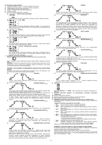
7- Pushbutton for the selection of parameters to be set.
Pushbutton
selects the parameter to be adjusted through the Encoder knob
(9)
;
the value and unit of measure are shown respectively on display
(10)
and led
(11)
.
N.B.:
The setting of parameters is free. Nevertheless, there are value combinations
that don’t have any practical meaning for the welding; in this case the welding
machine could operate incorrectly.
N.B.: RE-SETTING OF ALL FACTORY PARAMETERS (RESET)
Press all buttons (8) together at start-up to reset the welding parameters to default
settings.
7a
PRE-GAS
In TIG/HF mode it represents the PRE-GAS time in seconds (adjustment
range from 0÷5 seconds). It improves the welding start.
7b
START CURRENT (I
START
)
In TIG 2-stroke and SPOT modes this represents the start current I
S
maintained
for a set time with the torch button pressed (regulation in Ampere).
In 4-stroke TIG mode it represents the initial current Is maintained for the whole
time during which the torch pushbutton is pressed (adjustment in Amperes).
In MMA mode it represents the “HOT START” dynamic over-current (adjustment
range 0÷100%) with indication on display of the percentage increase in relation
to the value of the pre-selected welding current. This adjustment improves the
weld fluidity.
7c
INITIAL SLOPE (t
START
)
In TIG mode this represents the start current slope up time (from I
S
to I
2
)
(adjustment 0.1÷10sec.). The slope is no present when switched OFF.
7d
MAIN CURRENT (I
2
)
In TIG AC/DC and in the MMA modes, it represents the output current I
2
. In
PULSED and in BI-LEVEL modes it is the highest level current (maximum).
The parameter is measured in Amperes.
7e
BASE CURRENT - ARC FORCE
In 4-stroke TIG in the BI-LEVEL and in PULSED modes, I
1
represents the
value of the current, which can be alternated to the main I
2
during welding. The
value is expressed in Amperes.
In MMA mode, it represents the “ARC-FORCE” dynamic over-current
(adjustment range 0÷100%) with indication on display of the percentage
increase in relation to the value of the pre-selected welding current. This
adjustment improves the weld fluidity and avoids the electrode sticking to the
piece being welded.
7f
FREQUENCY
In PULSED TIG mode, it represents the pulsing frequency. For the AC/DC
models, in the TIG AC mode (with pulsing disabled) it represents the welding
current’s frequency.
7g
BALANCE
In PULSED TIG mode, it represents the ratio (in percentage) between the
time in which the current is found at maximum level (main welding current)
and the period of total pulsing. Furthermore, for the AC/DC models, in TIG AC
mode (with pulsing disabled), the parameter represented indicates the ratio
(in percentage) between the time in which the polarity of the current in output
from EN- (negative electrode) and the total period of the alternate current. The
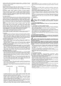
greater the value of EN-, the greater the penetration (adjustment in %)
(TAB.
4)
.
7h
SPOT TIME
In TIG (SPOT) mode, it represents the duration of the welding (adjustment
range 0.1÷10sec.).
7k
END SLOPE (t
END
)
In TIG mode this represents the final current slope down time (from I
2
a I
e
)
(adjustment 0.1÷10sec.). The slope is not present when switched OFF.
7l
END CURRENT (I
END
)
In TIG 2-stroke mode, it represents the end current I
e
only if the END SLOPE
(7k)
is set on a value greater than zero (>0.1 sec.).
In TIG 4-stroke mode, it represents the end current I
e
for the whole time during
which the torch pushbutton is pressed.
Magnitudes are expressed in Amperes.
7m
POSTGAS
In TIG mode, it represents the POSTGAS time in seconds (adjustment range
0.1÷25sec.) and protects the electrode and the weld pool from oxidation.
7n
ELECTRODE PREHEATING
In TIG mode, AC represents the result of the current multiplied by the Tungsten
electrode preheating time from when the arc is switched on.
8- JOB
“RECALL”
and
“SAVE”
pushbuttons to store and recall personalised programs.
9- Encoder knob for the setting of welding parameters that can be selected by
means of button (7).
10-
Alphanumeric display.
11-
Red led, indication of the unit of measure.
12-
Green led, power on.
13-
ALARM signalling LED (the machine is blocked).
Reset is automatic upon the cessation of the alarm motive.
Alarm messages appear on display
(10)
:
- ”AL1” :
primary circuit thermal protection tripping.
- ”AL2” :
secondary circuit thermal protection tripping.
- ”AL3” :
power supply
line protection against over-voltage tripping.
- ”AL4” :
power supply
line protection against under-voltage tripping.
- ”AL5” :
primary over-temperature protection tripping.
-
”AL6” :
protection tripping for power supply line phase missing.
-
”AL7” :
excessive deposit of dust within the welding machine, resetting by:
- inner cleaning of the machine;
- control panel display button.
-
”AL8” :
Auxiliary voltage out of range.
-
”AL9” :
safeguard triggered due to low pressure in water-cooled circuit in
torch. Resetting is not automatic.
Upon switching off of the welding machine, the
”OFF”
signalling could continue for
several seconds
N.B.: ALARMS STORING AND DISPLAY
With every alarm the machine’s settings are recorded. It is possible to recall the
last 10 alarms as follows:
Press pushbutton
(6a)
“REMOTE COMMAND” for a few seconds.
Code “AY.X” is displayed, where “Y” indicates the alarm number (A0 most recent,
A9 oldest) and “X” indicates the type of alarm recorded (from 1 to 8, see AL1 ...


