Сварочное оборудование Telwin SUPERIOR TIG 422 AC DC HF LIFT - инструкция пользователя по применению, эксплуатации и установке на русском языке. Мы надеемся, она поможет вам решить возникшие у вас вопросы при эксплуатации техники.
Если остались вопросы, задайте их в комментариях после инструкции.
"Загружаем инструкцию", означает, что нужно подождать пока файл загрузится и можно будет его читать онлайн. Некоторые инструкции очень большие и время их появления зависит от вашей скорости интернета.


- 8 -
AL8).
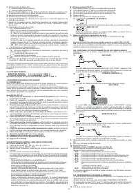
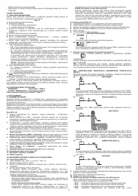
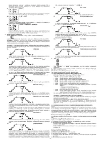
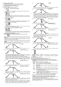
4.3 STORING AND RECALLING OF PERSONALISED PROGRAMS
Introduction
The welding machine allows the storing (SAVE) of personalised work programs relative
to a set of parameters applicable to a defined welding process. Each personalised
program can be accessed (RECALL) at any time thus allowing the user to have the
welding machine “ready for use” for a specific work cycle optimised previously. The
welding machine allows the saving of up to 9 personalised programs.
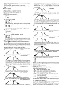
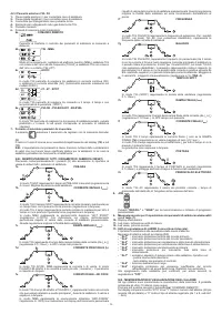
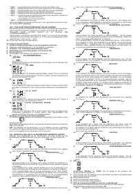
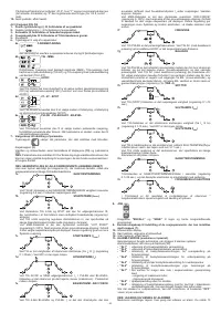
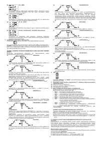
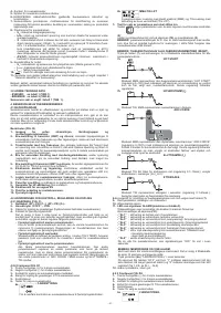
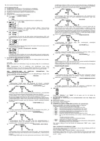
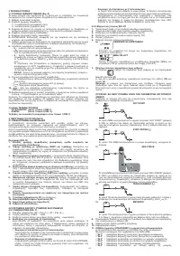
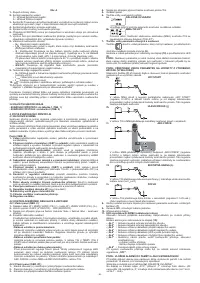
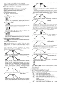
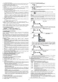
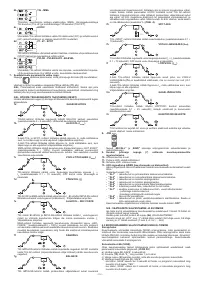
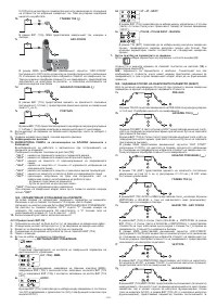
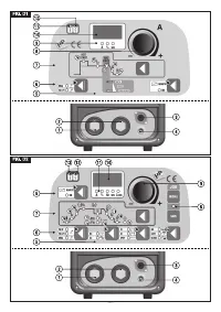
Storing procedure (SAVE)
After having adjusted the welding machine with an optimal set-up for a specific type of
welding job, proceed as follows (
FIG. D2
):
a) Press the “SAVE” button
(8)
for 3 seconds.
b) Code “S_ ” is displayed
(10)
together with a number ranging between 1 and 9.
c) By rotating knob
(9),
select the number with which the program is going to be
stored.
d) Press the “SAVE” button
(8)
again:
- if the “SAVE” button is pressed for more than 3 seconds, the program is correctly
stored and caption “YES” is displayed;
- if the “SAVE” button is pressed for less than 3 seconds, the program does not get
stored and caption “no” is displayed.
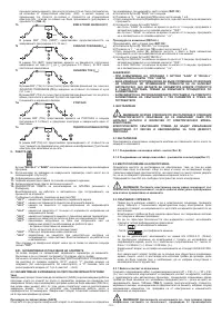
Recalling procedure (RECALL)
Proceed as follows (see
FIG. D2
):
a) Press the “RECALL” button
(8)
for 3 seconds.
b) “r_ ” appears on display
(10)
together with a number between 1 and 9.
c) By rotating knob
(9),
select the number with which the program that we now intend
using was stored.
d) Press “RECALL” button
(8)
again:
- if the “RECALL” button is pressed for more than 3 seconds, the program is
correctly recalled and caption “YES” is displayed;
- if the “RECALL” button is pressed for less than 3 seconds, the program does not
get recalled correctly and caption “no” is displayed.
NOTES:
- DURING OPERATIONS WITH THE “SAVE” AND “RECALL” BUTTONS, LED
“PRG” IS SWITCHED ON.
- A RECALLED PROGRAM CAN BE MODIFIED AT WILL BY THE OPERATOR,
BUT THE MODIFIED VALUES ARE NOT AUTOMATICALLY STORED. SHOULD
THE NEW VALUES ON THE SAME PROGRAM HAVE TO BE STORED, THE
STORING PROCEDURE MUST BE PERFORMED.
- RECORDING OF PERSONALISED PROGRAMS RELATIVE TO THE
SCHEDULING (SAVING) OF ASSOCIATED PARAMETERS, IS THE USER’S
RESPONSIBILITY.
5. INSTALLATION
WARNING! CARRY OUT ALL INSTALLATION OPERATIONS AND
ELECTRICAL CONNECTIONS WITH THE WELDING MACHINE COMPLETELY
SWITCHED OFF AND DISCONNECTED FROM THE POWER SUPPLY OUTLET.
THE ELECTRICAL CONNECTIONS MUST BE MADE ONLY AND EXCLUSIVELY
BY AUTHORISED OR QUALIFIED PERSONNEL.
5.1 PREPARATION
Unpack the welding machine, assemble the separate parts contained in the package.
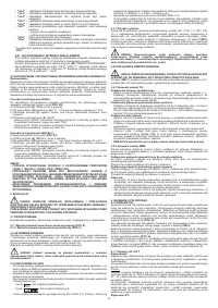
5.1.1 Assembling the return cable-clamp (FIG. E)
5.1.2 Assembling the welding cable-electrode holder clamp (FIG. E)
5.2 POSITION OF THE WELDING MACHINE
Choose the place to install the welding machine so that the cooling air inlets and
outlets are not obstructed (forced circulation by fan, if present); at the same time make
sure that conductive dusts, corrosive vapours, humidity etc. will not be sucked into
the machine.
Leave at least 250mm free space around the welding machine.
WARNING! Position the welding machine on a flat surface with
sufficient carrying capacity for its weight, to prevent it from tipping or moving
hazardously.
5.3 CONNECTION TO THE MAIN POWER SUPPLY
- Before making any electrical connection, make sure the rating data of the welding
machine correspond to the mains voltage and frequency available at the place of
installation.
- The welding machine should only be connected to a power supply system with the
neutral conductor connected to earth.
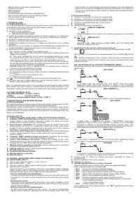
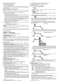
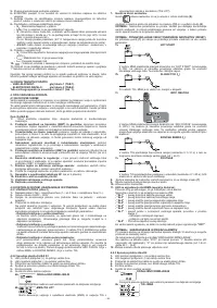
- To ensure protection against indirect contact use residual current devices of the
following types:
- Type A (
) for single phase machines;
- Type B (
) for 3-phase machines.
- To comply with the requirements of the EN 61000-3-11 (Flicker) standard we
recommend connecting the welding machine to interface points of the power supply
that have an impedance of less than Zmax = 0.228ohm (1~), Zmax = 0.283ohm
(3~).
- The welding machine does not fall within the requisites of IEC/EN 61000-3-12
standard.
Should it be connected to a public mains system, it is the installer’s responsibility
to verify that the welding machine itself is suitable for connecting to it (if necessary,
consult the distribution network company).
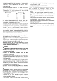
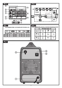
5.3.1 Plug and outlet
Connect a normalised plug (2P + P.E) (1~); (3P + P.E) (3~) - having sufficient capacity-
to the power cable and prepare a mains outlet fitted with fuses or an automatic circuit-
breaker; the special earth terminal should be connected to the earth conductor (yellow-
green) of the power supply line. Table
(TAB.1)
shows the recommended delayed fuse
sizes in amps, chosen according to the max. nominal current supplied by the welding
machine, and the nominal voltage of the main power supply.
WARNING! Failure to observe the above rules will make the (Class 1)
safety system installed by the manufacturer ineffective with consequent serious
risks to persons (e.g. electric shock) and objects (e.g. fire).
5.4 CONNECTION OF THE WELDING CABLES
WARNING! BEFORE MAKING THE FOLLOWING CONNECTIONS MAKE
SURE THE WELDING MACHINE IS SWITCHED OFF AND DISCONNECTED FROM
THE POWER SUPPLY OUTLET.
Table
(TAB. 1)
gives the recommended values for the welding cables (in mm
2
)
depending on the maximum current supplied by the welding machine.
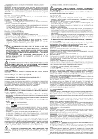
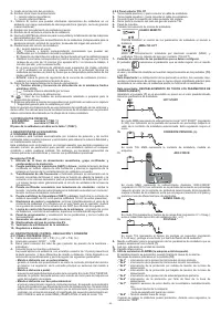
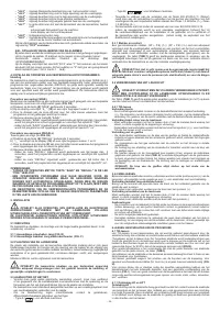
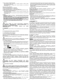
5.4.1 TIG welding
Connecting the torch
- Insert the torch current cable into the appropriate quick terminal (-)/~. Connect the
three-pin connector (torch button) to the appropriate socket. Connect the torch gas
pipe to the appropriate connector.
Connecting the welding current return cable
- This is connected to the piece to be welded or to the metal bench on which it rests,
as close as possible to the joint being made.
This cable is connected to the terminal with the (+) symbol (~ for TIG machines
designed for AC welding).
Connecting the gas bottle
- Screw the pressure reducing valve to the gas bottle valve, first inserting the special
reduction accessory supplied when argon gas is used.
- Connect the gas inflow hose to the pressure reducing valve and tighten the hose
clamp supplied.
- Loosen the ringnut for adjusting the pressure reducing valve before opening the
valve on the bottle.
- Open the valve on the bottle and adjust the quantity of gas (l/min) according to the
suggestions for use given in the table
(TAB. 4)
; if it is necessary to adjust the gas flow
during welding this should always be done by adjusting the ring nut on the pressure
reduction valve. Make sure there are no leaks in the piping and connectors.
WARNING! Always close the gas bottle valve at the end of the job.
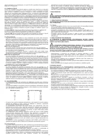
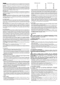
5.4.2 MMA WELDING
Almost all coated electrodes are connected to the positive pole (+) of the power source;
as an exception to the negative pole (-) for acid coated electrodes.
Connecting the electrode-holder clamp welding cable
On the end take a special terminal that is used to close the uncovered part of the
electrode.
This cable is connected to the terminal with the symbol (+)
Connecting the welding current return cable
This is connected to the piece being welded or to the metal bench supporting it, as
close as possible to the join being made.
This cable is connected to the terminal with the symbol (-)
Warnings:
- Turn the welding cable connectors right down into the quick connections (if present),
to ensure a perfect electrical contact; otherwise the connectors themselves will
overheat, resulting in their rapid deterioration and loss of efficiency.
- The welding cables should be as short as possible.
- Do not use metal structures which are not part of the workpiece to substitute the
return cable of the welding current: this could jeopardise safety and result in poor
welding.
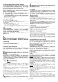
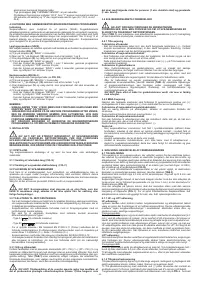
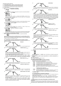
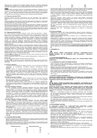
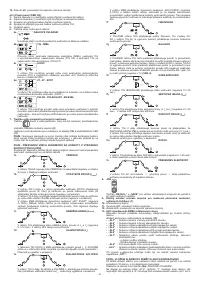
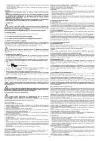
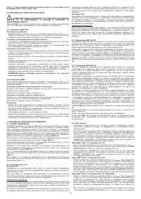
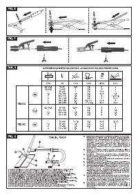
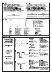
6. WELDING: DESCRIPTION OF THE PROCEDURE
6.1 TIG WELDING
TIG welding is a welding procedure that exploits the heat produced by the electric arc
that is struck, and maintained, between a non-consumable electrode (tungsten) and
the piece to be welded. The tungsten electrode is supported by a torch suitable for
transmitting the welding current to it and protecting the electrode itself and the weld
pool from atmospheric oxidation, by the flow of an inert gas (usually argon: Ar 99.5)
which flows out of the ceramic nozzle
(FIG. G)
.
To achieve a good weld it is absolutely necessary to use the exact electrode diameter
with the exact current, see the table
(TAB. 3).
The electrode usually protrudes from the ceramic nozzle by 2-3mm, but this may reach
8mm for corner welding.
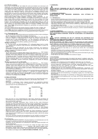
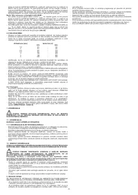
Welding is achieved by fusion of the edges of the joint. For properly prepared thin
pieces (up to about 1mm) weld material is not needed
(FIG. H)
.
For thicker pieces it is necessary to use filler rods of the same composition as the base
material and with an appropriate diameter, preparing the edges correctly
(FIG. I)
. To
achieve a good weld the pieces should be carefully cleaned and free of oxidation, oil,
grease, solvents etc.
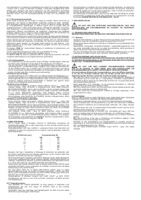
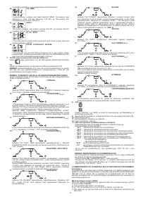
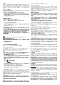
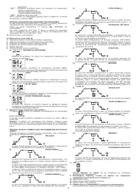
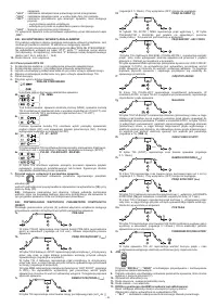
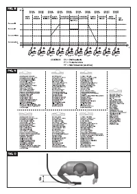
6.1.1 HF and LIFT strike
HF strike:
The electric arc is struck without contact between the tungsten electrode and the piece
being welded, by means of a spark generated by a high frequency device. This strike
mode does not entail either tungsten inclusions in the weld pool or electrode wear and
gives an easy start in all welding positions.
Procedure:
Press the torch button, bringing the tip of the electrode close to the piece (2 -3mm),
wait for the arc strike transferred by the HF pulses and, when the arch has struck, form
the weld pool on the piece and proceed along the joint.
If there are difficulties in striking the arc even though the presence of gas is confirmed
and the HF discharges are visible, do not insist for long in subjecting the electrode to
HF action, but check the integrity of the surface and the shape of the tip, dressing it
on the grinding wheel if necessary. At the end of the cycle the current will fall at the
slope down setting.
LIFT strike:
The electric arc is struck by moving the tungsten electrode away from the piece to
be welded. This strike mode causes less electrical-radiation disturbance and reduces
tungsten inclusions and electrode wear to a minimum.
Procedure:
Place the tip of the electrode on the piece, using gentle pressure. Press the torch
button right down and lift the electrode 2-3mm with a few moments’ delay, thus striking
the arc. Initially the welding machine supplies a current I
LIFT
, after a few moments the
welding current setting will be supplied. At the end of the cycle the current will fall to
zero at the slope down setting.
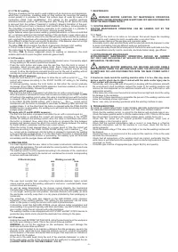
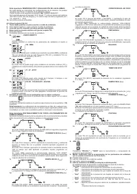
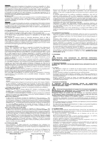
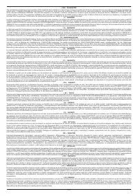
6.1.2 TIG DC welding
TIG DC welding is suitable for all low- and high-carbon steels and the heavy metals,
copper, nickel, titanium and their alloys.
For TIG DC welding with the electrode to the (-) terminal the electrode with 2% thorium
(red band) is usually used or else the electrode with 2% cerium (grey band).
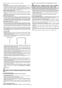
It is necessary to sharpen the tungsten electrode axially on the grinding wheel,
as shown in
FIG. L
,
making sure that the tip is perfectly concentric to prevent arc
deviation. It is important to carry out the grinding along the length of the electrode.
This operation should be repeated periodically, depending on the amount of use and
wear of the electrode, or when the electrode has been accidentally contaminated,
oxidised or used incorrectly. In TIG DC mode 2-stroke (2T) and 4-stroke(4T) operation
are possible.


