Сварочное оборудование Telwin SUPERIOR TIG 422 AC DC HF LIFT - инструкция пользователя по применению, эксплуатации и установке на русском языке. Мы надеемся, она поможет вам решить возникшие у вас вопросы при эксплуатации техники.
Если остались вопросы, задайте их в комментариях после инструкции.
"Загружаем инструкцию", означает, что нужно подождать пока файл загрузится и можно будет его читать онлайн. Некоторые инструкции очень большие и время их появления зависит от вашей скорости интернета.


- 6 -
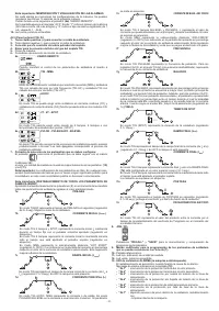
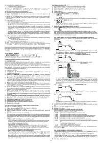
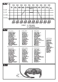
- Manual remote control with 2 potentiometers.
- Pedal remote control.
- MMA welding kit.
- TIG welding kit.
- Self-darkening mask: with fixed or adjustable filter.
- Gas connector and pipe for hook-up with Argon bottle.
- Pressure reducing valve with gauge.
- Torch for TIG welding.
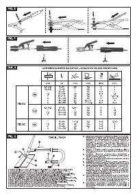
3. TECHNICAL DATA
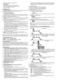
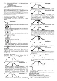
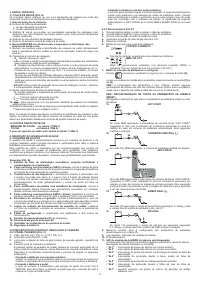
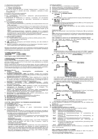
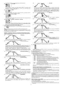
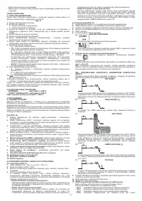
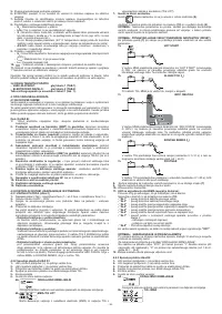
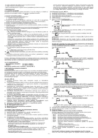
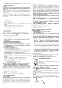
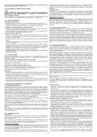
3.1 DATA PLATE (FIG. A)
The most important data regarding use and performance of the welding machine are
summarised on the rating plate and have the following meaning:
1-
Protection rating of the covering.
2-
Symbol for power supply line:
1~: single phase alternating voltage;
3~: three phase alternating voltage.
3-
Symbol
S
: indicates that welding operations may be carried out in environments
with heightened risk of electric shock (e.g. very close to large metallic volumes).
4-
Symbol for welding procedure provided.
5-
Symbol for internal structure of the welding machine.
6-
EUROPEAN standard of reference, for safety and construction of arc welding
machines.
7-
Manufacturer’s serial number for welding machine identification (indispensable for
technical assistance, requesting spare parts, discovering product origin).
8-
Performance of the welding circuit:
- U
0
:
maximum no-load voltage (open welding circuit).
- I
2
/U
2
:
current and corresponding normalised voltage that the welding machine can
supply during welding.
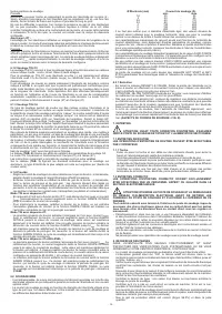
- X :
Duty cycle: indicates the time for which the welding machine can supply
the corresponding current (same column). It is expressed as %, based on a 10
minutes cycle (e.g. 60% = 6 minutes working, 4 minutes pause, and so on).
If the usage factors (on the plate, referring to a 40°C environment) are exceeded,
the thermal safeguard will trigger (the welding machine will remain in standby until
its temperature returns within the allowed limits).
- A/V-A/V:
shows the range of adjustment for the welding current (minimum
maximum) at the corresponding arc voltage.
9-
Technical specifications for power supply line:
- U
1
:
Alternating voltage and power supply frequency of welding machine (allowed
limit ±10%).
- I
1 max
:
Maximum current absorbed by the line.
- I
1eff
:
Effective current supplied.
10-
:
Size of delayed action fuses to be used to protect the power line.
11-
Symbols referring to safety regulations, whose meaning is given in chapter 1
“General safety considerations for arc welding”.
Note: The data plate shown above is an example to give the meaning of the symbols
and numbers; the exact values of technical data for the welding machine in your
possession must be checked directly on the data plate of the welding machine itself.
3.2 OTHER TECHNICAL DATA
- WELDING MACHINE: see table 1 (TAB.1).
- TORCH:
see table 2 (TAB.2).
The welding machine weight is shown in table 1 (TAB. 1).
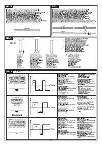
4. DESCRIPTION OF THE WELDING MACHINE
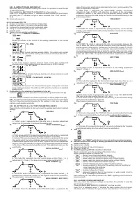
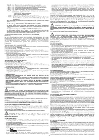
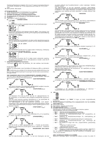
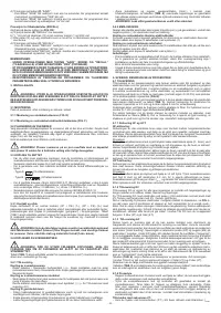
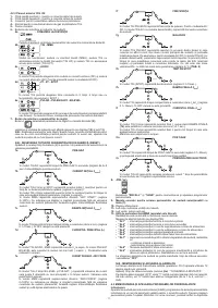
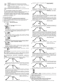
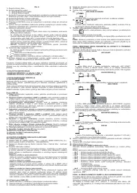
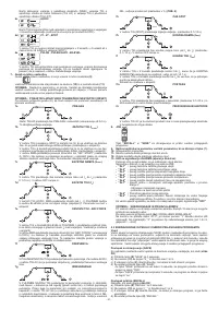
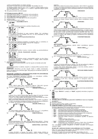
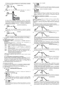
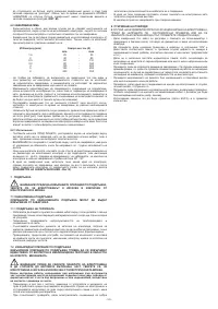
4.1 BLOCK DIAGRAM
The welding machine consists basically of power and control modules made on PCB’s
and optimised to achieve perfect reliability and reduced maintenance.
This welding machine is controlled by a microprocessor that allows a large number
of parameter settings so as to achieve perfect welding in any condition and with any
material. However, to make the best use of its properties it is necessary to be fully
aware of its possibilities.
Description (FIG. B)
1- Single phase power supply input, rectifier unit and levelling capacitors.
2- Transistor (IGBT) switching bridge and drivers;
commutes the rectified power
supply voltage to high frequency alternating voltage and adjusts the power
according to the required welding current/voltage.
3- High frequency transformer;
the voltage converted by block 2 powers the
primary winding; its function is to adjust the voltage and current to the values
needed for the arc welding procedure and at the same time to form galvanic
separation of the welding circuit from the power supply line.
4- Secondary rectifier bridge with levelling inductance;
commutes the alternating
voltage / current supplied by the secondary winding into very low ripple direct
current / voltage.
5- Transistor (IGBT) switching bridge and drivers;
transforms the secondary
output current from DC to AC for TIG AC welding (if present).
6- Control and adjustment electronics;
controls the welding current value
instantaneously and compares it with the operator’s setting; modulates the control
impulses from the IGBT drivers that make the adjustment.
7- Welding machine operation control logic;
sets the welding cycles, controls the
actuators, supervises the safety systems.
8- Settings panel
and display of parameters and operating modes.
9-
HF strike generator
(if present)
.
10- Protective gas solenoid valve EV.
11- Welding machine cooling fan.
12- Remote control.
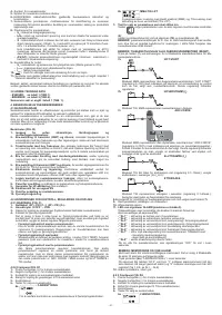
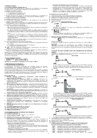
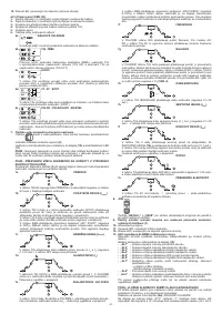
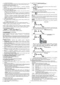
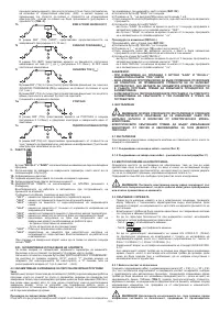
4.2 CONTROL, ADJUSTMENT AND CONNECTION DEVICES
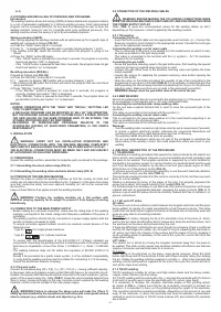
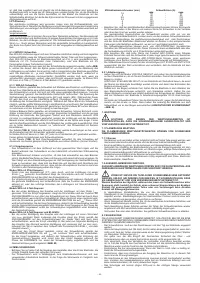
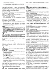
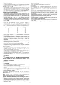
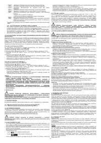
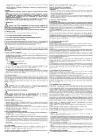
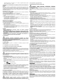
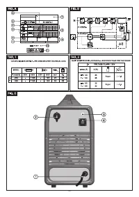
4.2.1 BACK PANEL (FIG. C)
1-
Power supply cable (2P + P.E) (1~); (3P + P.E) (3~).
2-
Main switch O/OFF - I/ON.
3-
Gas pipe connector (bottle pressure reducing valve welding machine).
4-
Remote control connector:
Using the special 14-pin connector on the back, it is possible to attach 3 different
types of remote control to the welding machine. Each device will be recognised
automatically and can be used to adjust the following parameters:
- Remote control with one potentiometer:
turning the potentiometer knob will change the main current from the minimum to
the maximum. The main current is adjusted only and exclusively by the remote
control.
- Pedal remote control:
The current value is determined by the position of the pedal. In addition, in TIG
2-STROKE mode pressing the pedal gives the start command to the machine
instead of the torch button.
- Remote control with two potentiometers:
the first potentiometer adjusts the main current. The second potentiometer
adjusts another parameter, depending on the active welding mode. When this
potentiometer is turned the display will show the changing value of the parameter
(which can no longer be controlled with the knob on the panel). The meaning of
the second potentiometer is: ARC FORCE if in MMA mode and END SLOPE if
in TIG mode.
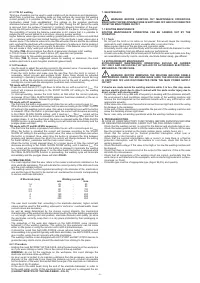
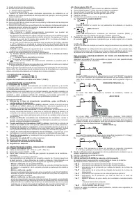
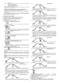
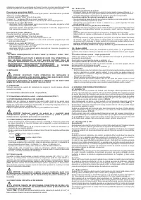
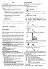
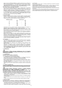
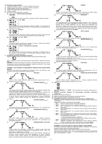
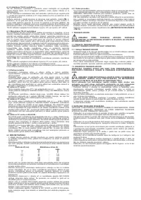
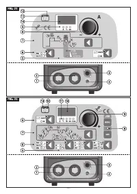
4.2.2 Front panel FIG. D1
1-
Positive (+) quick latch to connect the welding cable.
2-
Negative (-) quick latch to connect the welding cable.
3-
Connector for connecting the torch pushbutton cable.
4-
Fitting for connecting the gas pipe of the TIG torch.
5-
Controls panel.
6-
Welding modes selection pushbuttons:
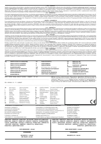
6a
REMOTE COMMAND
Allows the transfer of the control of the welding parameters to the remote
control.
6b
MMA-TIG LIFT
Operating mode: coated electrode welding (MMA), and TIG welding with
contact arc lift strike (TIG LIFT).
7- Pushbutton for the selection of parameters to be set.
Button
selects the parameter to be adjusted through Encoder knob
(8)
;
the value and unit of measure are visualised respectively on display
(10)
and led
(9)
.
N.B.:
Setting of parameters is free. However, there are value combinations that
have no practical meaning for the welding; in this case the welding machine could
operate incorrectly.
N.B.:
RE-SETTING OF ALL FACTORY PARAMETERS (RESET)
By pressing pushbutton
(7)
at switch-on, all welding parameters are returned to
default value.
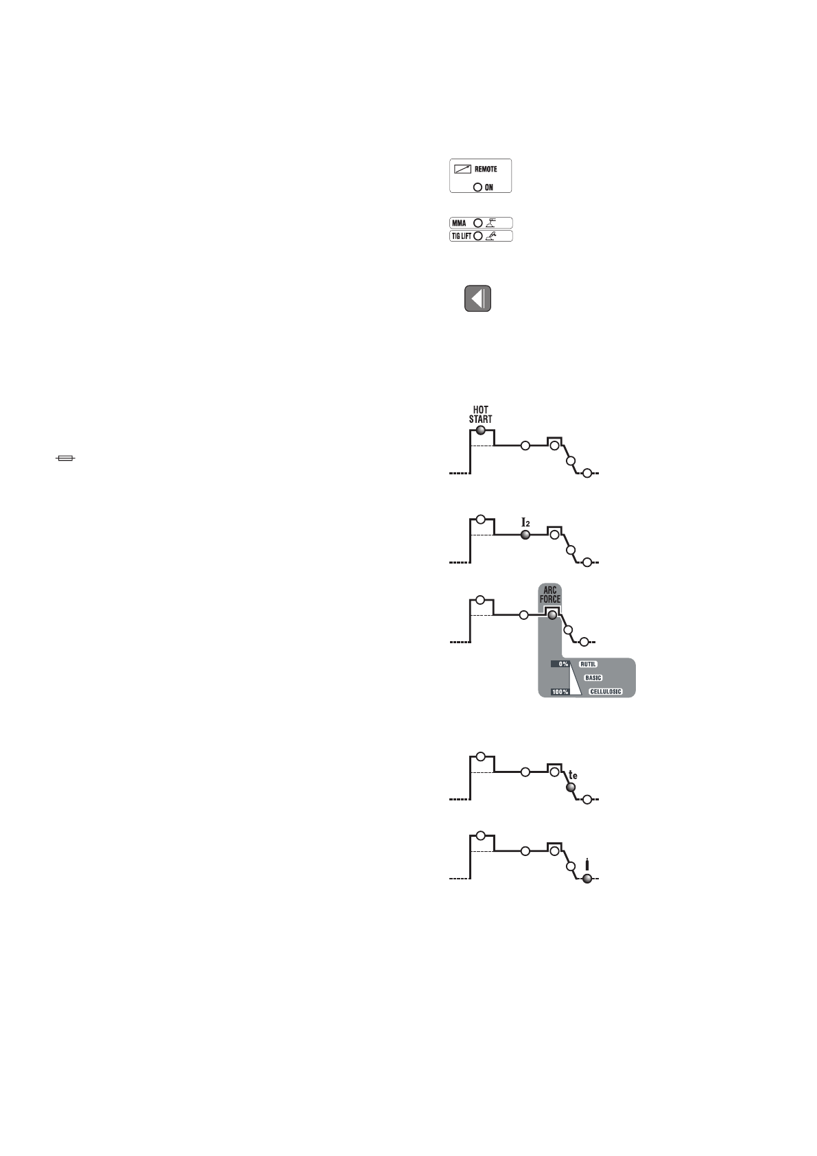
7a
HOT START
In the MMA mode, this represents the “HOT START” initial over-current
(adjustment range 0÷100) with indication on display of the percentage
increment of the selected welding current. This adjustment improves start-up.
7b
MAIN CURRENT (I
2
)
In TIG mode, MMA represents the welding current, measured in Amperes.
7c
ARC-FORCE
In MMA mode, it represents the dynamic “ARC-FORCE” over-current
(adjustment range 0÷100%) with indication on display of the percentage
increment in relation to the pre-selected welding current’s value. This
adjustment improves the weld fluidity, avoids the electrode sticking to the piece
being welded and allows the use of different types of electrodes.
7d
END SLOPE (t
e
)
In TIG mode, it represents the time for the end slope (adjustment range
0.1÷10sec.); it avoids the weld seam’s end crater (from I
2
to 0).
7e
POSTGAS
In TIG mode, it represents the time for postgas in seconds (adjustment range
0.1÷25sec.); it protects the weld pool from oxidation.
8-
Encoder knob for setting the welding parameters, selectable by means of
pushbutton
(7)
.
9-
Red led, indication of the unit of measure.
10-
Alphanumeric display.
11-
ALARM-signalling LED (the machine is blocked).
Reset is automatic upon cessation of the cause that triggered the alarm.
Alarm messages appearing on display
(10)
:
- ”AL1” :
primary circuit thermal protection tripping.
- ”AL2” :
secondary circuit thermal protection tripping.
- ”AL3” :
power supply
line protection against over-voltage tripping.
- ”AL4” :
power supply
line protection against under-voltage tripping.
- ”AL5” :
primary over-temperature protection tripping.
-
”AL6” :
protection tripping for power supply
line phase missing.
-
”AL7” :
excessive deposit of dust within the welding machine, resetting by:
- inner cleaning of machine;
- control panel display button.
-
”AL8” :
Auxiliary voltage out of range.
Upon switching off of the welding machine, the
”OFF”
signalling could continue
for several seconds.


