Электропилы Bosch GCM 12 GDL - инструкция пользователя по применению, эксплуатации и установке на русском языке. Мы надеемся, она поможет вам решить возникшие у вас вопросы при эксплуатации техники.
Если остались вопросы, задайте их в комментариях после инструкции.
"Загружаем инструкцию", означает, что нужно подождать пока файл загрузится и можно будет его читать онлайн. Некоторые инструкции очень большие и время их появления зависит от вашей скорости интернета.


English |
43
Bosch Power Tools
1 609 92A 0XN | (13.10.14)
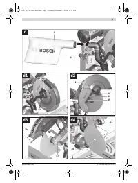
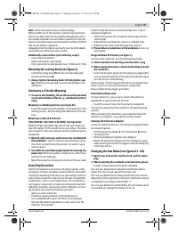
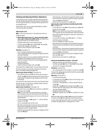
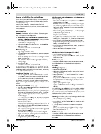
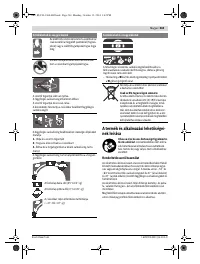
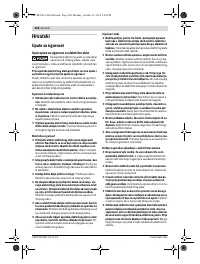
Checking and Adjusting the Basic Adjustment
To ensure precise cuts, the basic adjustment of the machine
must be checked and adjusted as necessary after intensive use.
A certain level of experience and appropriate specialty tools
are required for this.
A Bosch after-sales service station will handle this mainte-
nance task quickly and reliably.
Adjusting the Laser
Note:
To test the laser function, the machine must be con-
nected to power.
While adjusting the laser (e.g. when moving the glide
arm), never actuate the On/Off switch.
Accidental start-
ing of the power tool can lead to injuries.
– Bring the power tool into the working position.
– Turn the saw table
38
to the 0 ° detent
18
. The lever
16
must be felt to engage in the detent.
– Switch on the laser beams with switch
61
.
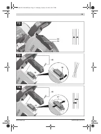
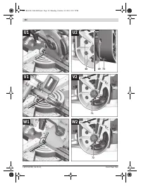
Checking:
(see figure T1)
– Draw a straight cutting line on the workpiece.
– Press locking lever
5
and slowly guide the glide arm down-
ward with handle
4
.
– Align the workpiece in such a manner that the teeth of the
saw blade are in alignment with the cutting line.
– Hold the workpiece in this position and slowly guide the
glide arm upward.
– Clamp the workpiece.
– Switch on the laser beams with switch
61
.
Throughout the complete length, the laser beams must have
the same clearance to the drawn cutting line on the work-
piece, even when lowering the glide arm.
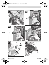
Adjusting the Flush Levelling:
(see figure T2)
– Using the hex key (2 mm)
21
, turn the respective adjust-
ment screw
64
until the laser beam has the same clearance
to the drawn cutting line on the workpiece over the com-
plete length.
One rotation in anticlockwise direction moves the laser beam
from left to right; one rotation in clockwise direction moves
the laser beam from right to left.
Adjusting the Parallelism:
(see figure T3)
– Loosen the two screws
65
of laser protection cap
27
with
the hex key (4 mm)
20
.
Note:
To access the front screw of the laser protection
cap, the glide arm must be tilted down a little until the hex
key can be inserted through one of the slots of the retract-
ing blade guard.
– Loosen fastening screw
66
(approx. 1 – 2 turns) with the
hex key (2 mm)
21
.
Do not completely unscrew the screw.
– Move the mounting plate of the laser right or left until the
laser beams are parallel to the drawn cutting line on the
workpiece over the complete length.
– Hold the mounting plate in this position and tighten fasten-
ing screw
66
again.
– After adjusting, check the flush alignment with the cutting
line once more. If required, align the laser beams with the
set screws
64
one more time.
– Reattach the laser protection cap
27
again.
Adjusting the Lateral Deviation when Moving the Glide
Arm:
(see figure T4)
– Loosen the two screws
65
of laser protection cap
27
with
the hex key (4 mm)
20
.
Note:
To access the front screw of the laser protection
cap, the glide arm must be tilted down a little until the hex
key can be inserted through one of the slots of the retract-
ing blade guard.
– Loosen both fastening screws
67
(approx. 1 – 2 turns)
with the hex key (2 mm)
21
.
Do not completely unscrew the screws.
– Move the laser housing right or left until the laser beams no
longer deviate in lateral direction when moving the glide
arm down.
– After adjusting, check the flush alignment with the cutting
line once more. If required, align the laser beams with the
set screws
64
one more time.
– Hold the laser housing in this position and tighten fasten-
ing screws
67
again.
– Reattach the laser protection cap
27
again.
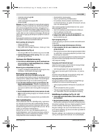
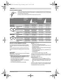
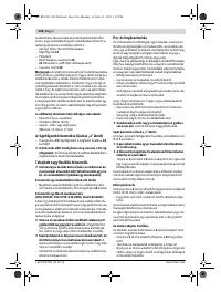
Setting the Standard Bevel Angle 0 ° (Vertical)
– Bring the machine into the transport position.
– Turn the saw table
38
to the 0 ° detent
18
. The lever
16
must be felt to engage in the detent.
Checking:
(see figure U1)
– Set an angle gauge to 90 ° and place it on the saw table
38
.
The leg of the angle gauge must be flush with the saw blade
40
over the complete length.
Adjusting:
(see figure U2)
– Loosen the lock lever
17
.
– Loosen both set screws
68
(by at least 1 turn) using a sock-
et spanner (size 10 mm).
– Loosen set screw
70
(approx. 3 turns) with the hex key
(4 mm)
20
.
– Screw set screw
69
with the hex key (4 mm)
20
in or out
until the leg of the angle gauge is flush with the saw blade
over the complete length.
– Retighten the lock lever
17
again.
Afterwards, tighten set screw
70
first, and then set screws
68
.
When the angle indicators
33
and
24
are not in line with the
0 ° marks of scale
32
after adjusting, loosen the fastening
screws of the angle indicators with a cross-head screwdriver
and align the angle indicators alongside the 0 ° marks.
OBJ_BUCH-1360-002.book Page 43 Monday, October 13, 2014 12:18 PM
Содержание
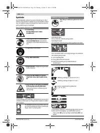
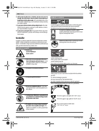
- 277 Защищайте электроинструмент от дождя и сырости.
- 278 Держите Ваше рабочее место в чистоте.
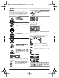
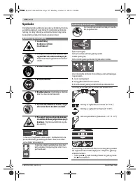
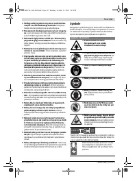
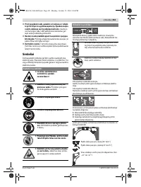
- 279 Закрепляйте заготовку.; Символы; Символы и их значение
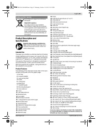
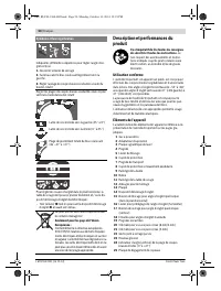
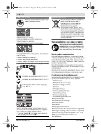
- 280 Описание продукта и услуг; Применение по назначению
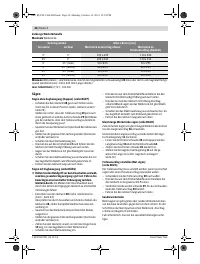
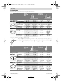
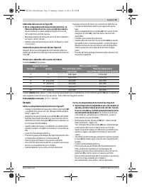
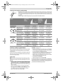
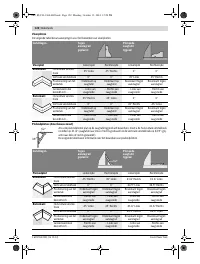
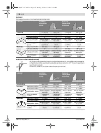
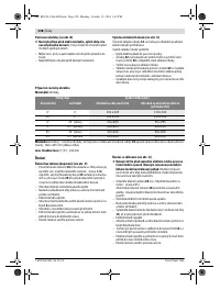
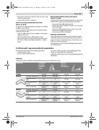
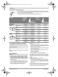
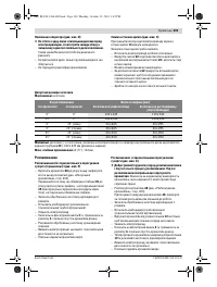
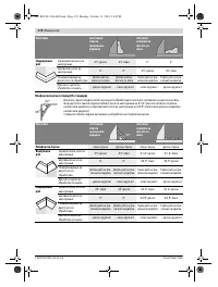
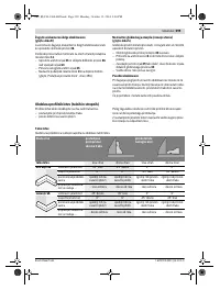
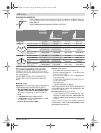
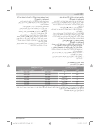
- 281 Технические данные; Применяйте средства защиты органов слуха!; Размеры пильных дисков
- 282 Заявление о соответствии; Сборка; Комплект поставки
- 283 Избегайте скопления пыли на рабочем месте.
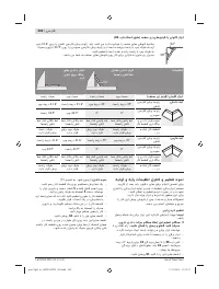
- 284 Работа с инструментом; Фиксация кронштейна; мягкого; более жесткого
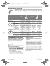
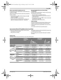
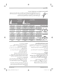
- 285 Настройка горизонтального угла распила; Стандартный угол распила 0 °
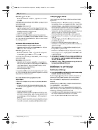
- 286 Включение электроинструмента
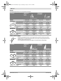
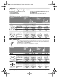
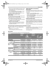
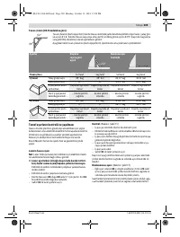
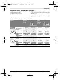
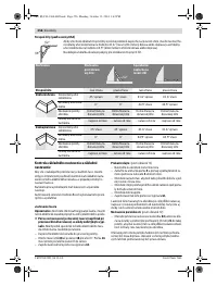
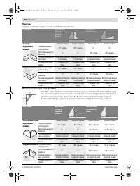
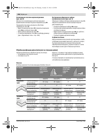
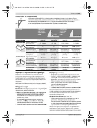
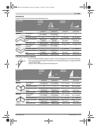
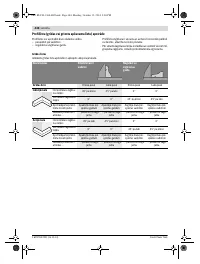
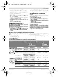
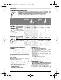
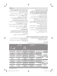
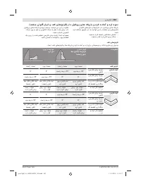
- 287 Минимальные; Пиление; Специальные заготовки
- 288 Плинтусы
- 289 Основные настройки – контроль и коррекция; Настройка ровности
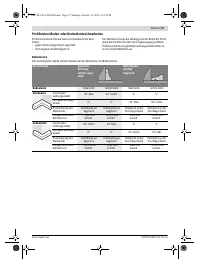
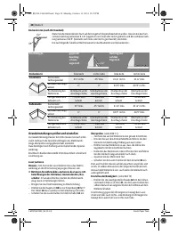
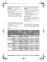
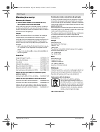
- 291 Техобслуживание и сервис; Техобслуживание и очистка; Очистка; Принадлежности; Пильные диски для пластмассы и цветных металлов
- 292 Россия; Утилизация


