Электропилы Bosch GCM 12 GDL - инструкция пользователя по применению, эксплуатации и установке на русском языке. Мы надеемся, она поможет вам решить возникшие у вас вопросы при эксплуатации техники.
Если остались вопросы, задайте их в комментариях после инструкции.
"Загружаем инструкцию", означает, что нужно подождать пока файл загрузится и можно будет его читать онлайн. Некоторые инструкции очень большие и время их появления зависит от вашей скорости интернета.


38
| English
1 609 92A 0XN | (13.10.14)
Bosch Power Tools
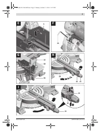
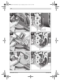
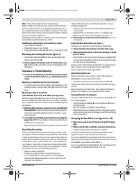
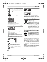
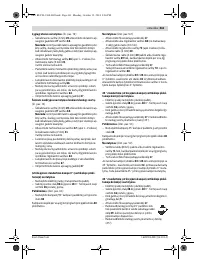
Removing the Saw Blade
– Bring the power tool into the working position.
– Unscrew locking screw
42
by hand until the linkage
43
can
hang freely.
– Loosen fastening screw
44
(approx. 2 turns) with the hex
key (4 mm)
20
.
Do not completely unscrew the screw.
– Loosen the fastening screw
45
(approx. 6 turns) with the
hex key (4 mm)
20
.
Do not completely unscrew the screw.
– Pull cover plate
46
off of fastening screw
45
toward the
front and bottom.
– Press locking lever
5
and swing back the retracting blade
guard
8
.
Hold the retracting blade guard in this position.
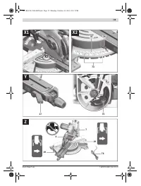
– Hang linkage
43
over fastening screw
45
via a bolt hole.
This holds the retracting blade guard in the open position.
– Turn the hex socket screw
48
with the hex key (6 mm)
20
and at the same time press the spindle lock
47
until it en-
gages.
– Hold the spindle lock
47
pressed and unscrew the hex
socket screw
48
in clockwise direction (left-hand thread!).
– Remove the clamping flange
49
.
– Remove the saw blade
40
.
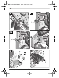
Mounting the Saw Blade
If required, clean all parts to be mounted prior to assembly.
– Place the new saw blade onto the interior clamping flange
50
.
When mounting the saw blade, pay attention that the
cutting direction of the teeth (arrow direction on the
saw blade) corresponds with the direction of the arrow
on the blade guard!
– Place on the clamping flange
49
and the screw
48
.
Press the spindle lock
47
until it engages and tighten the
screw turning in anticlockwise direction.
– Release linkage
43
from fastening screw
45
and guide the
retracting blade guard down again.
– Slide cover plate
46
under fastening screw
45
again.
– Retighten the fastening screws
45
and
44
again.
– Slide linkage
43
onto its original position and retighten
locking screw
42
by hand again.
Operation
Before any work on the machine itself, pull the mains
plug.
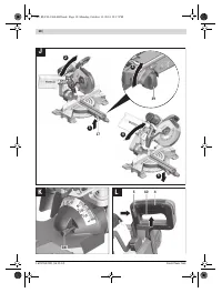
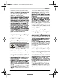
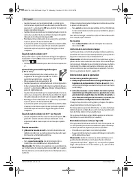
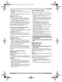
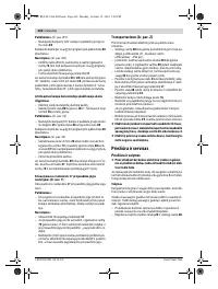
Transport Safety (see figure A)
The transport safety-lock
31
enables easier handling of the
machine when transporting to various working locations.
Releasing the Machine (Working Position)
– Slightly push down glide arm
28
by handle
4
to release
transport safety-lock
31
.
– Pull the transport safety-lock
31
completely outward.
– Slowly guide the glide arm upward.
Securing the Machine (Transport Position)
– Slide glide arm
28
completely to the rear and secure it in
this position (see “Securing the Glide Arm”, page 38).
– Guide the glide arm downward until transport safety-lock
31
can be pushed completely inward.
For additional information on transport, see page 44.
Locking the Glide Arm
The glide mechanism of glide arm
28
can be locked with lock
lever
26
. Two glide arm positions are possible:
– Glide arm pushed completely to the rear (for chop-cuts)
– Glide arm pulled completely to the front (for a compact
transport position)
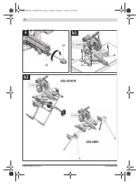
Releasing the Glide Arm (see figure B1)
After releasing the glide arm
28
, the complete pulling mecha-
nism is ready for operation.
– Push the lock lever
26
down to the stop.
The clamping wedge of the lock lever releases both bottom
joint parts of the glide arm.
Securing the Glide Arm (see figure B2)
Glide arm pushed completely to the rear:
– Push glide arm
28
toward the rear to the stop.
The two upper joint parts of the glide arm are now in the up-
right position and shut.
– Pull lock lever
26
upward until of the clamping wedge is po-
sitioned between the two bottom joint parts of the glide
arm.
This locks the completely pushed back glide arm
28
.
Glide arm pulled completely to the front:
– Pull glide arm
28
forward to the stop.
The glide mechanism is now completely extended.
– Pull lock lever
26
upward until of the clamping wedge is po-
sitioned between the two bottom joint parts of the glide
arm.
This locks the completely forward pulled glide arm
28
.
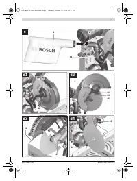
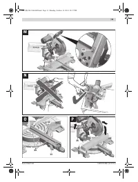
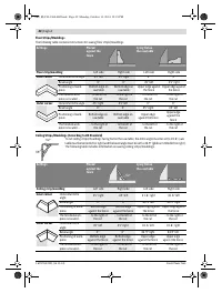
Preparing for Operation
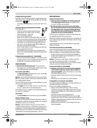
Extending the Saw Table (see figure C)
Long workpieces must be underlaid or supported at their free
end.
The saw table can be extended left and right with the saw-ta-
ble extensions
11
.
– Push clamping lever
51
inward.
– Pull out saw-table extension
11
to the desired length (max.
250 mm).
– To lock the saw-table extension, push clamping lever
51
outward again.
Extending the Fence (see figure D)
For bevel angles, the fence extensions
9
must be moved.
– Turn clamping lever
52
toward the front.
– Pull the fence extension
9
completely outward.
– To lock the adjustable fence, push clamping lever
52
down
again.
OBJ_BUCH-1360-002.book Page 38 Monday, October 13, 2014 12:18 PM
Содержание
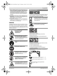
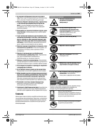
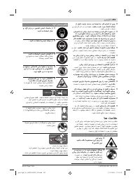
- 277 Защищайте электроинструмент от дождя и сырости.
- 278 Держите Ваше рабочее место в чистоте.
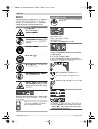
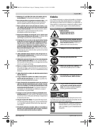
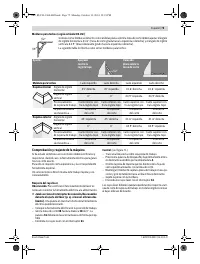
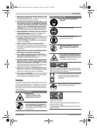
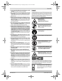
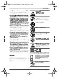
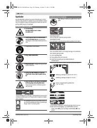
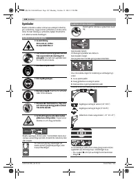
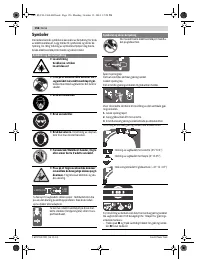
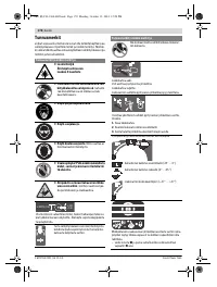
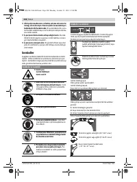
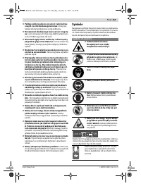
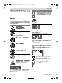
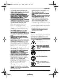
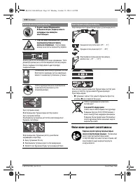
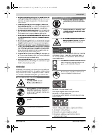
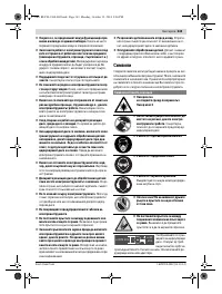
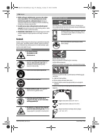
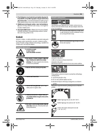
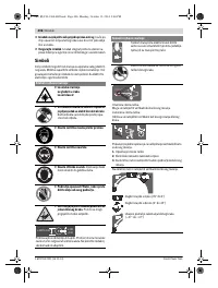
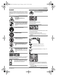
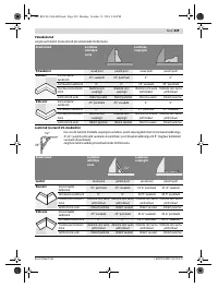
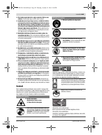
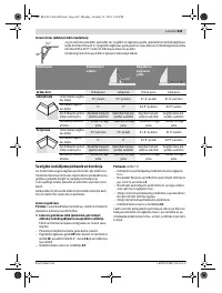
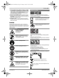
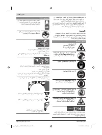
- 279 Закрепляйте заготовку.; Символы; Символы и их значение
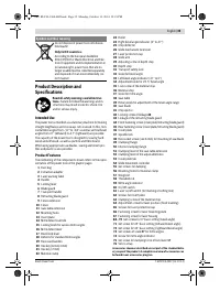
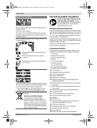
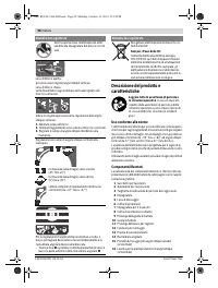
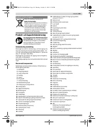
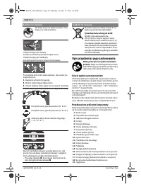
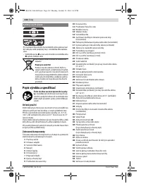
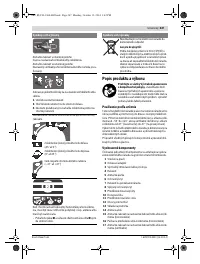
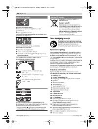
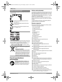
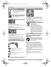
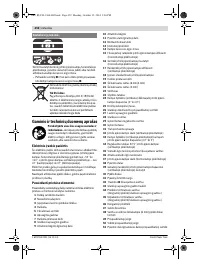
- 280 Описание продукта и услуг; Применение по назначению
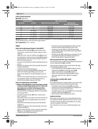
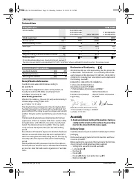
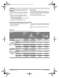
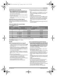
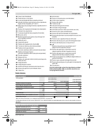
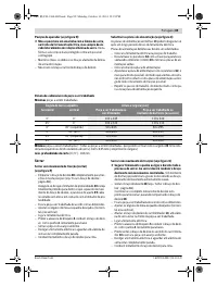
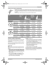
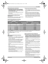
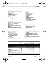
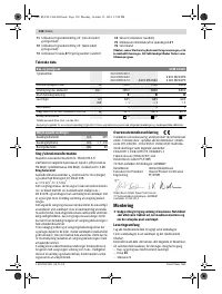
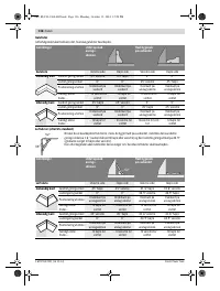
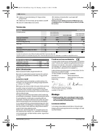
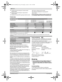
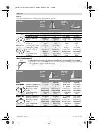
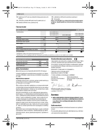
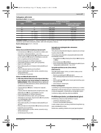
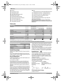
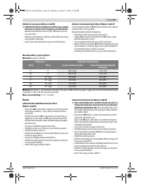
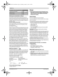
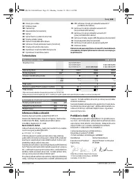
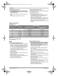
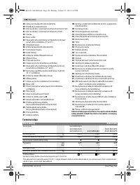
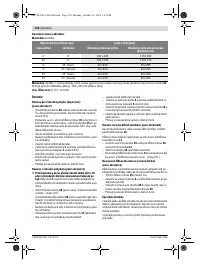
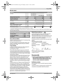
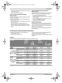
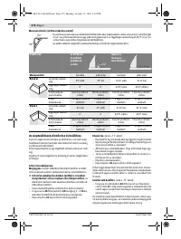
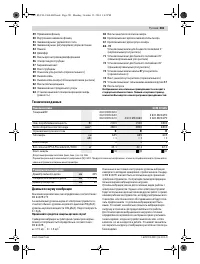
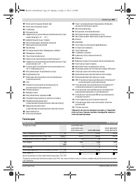
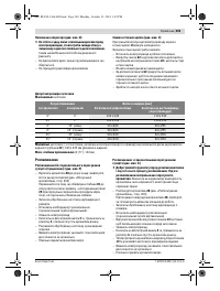
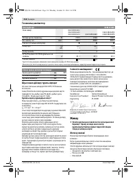
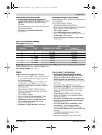
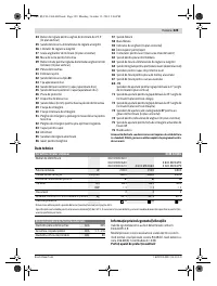
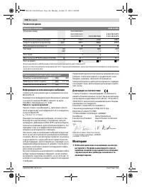
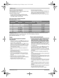
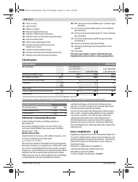
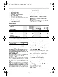
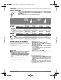
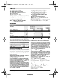
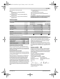
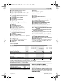
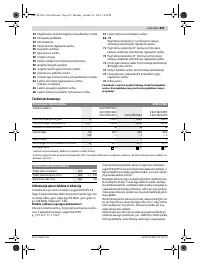
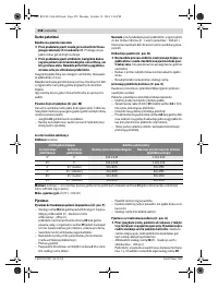
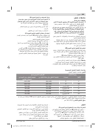
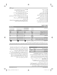
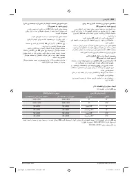
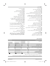
- 281 Технические данные; Применяйте средства защиты органов слуха!; Размеры пильных дисков
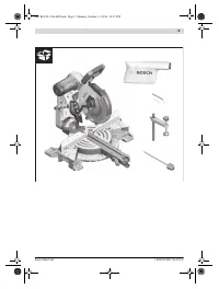
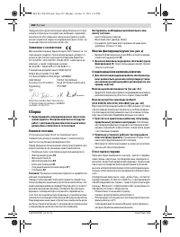
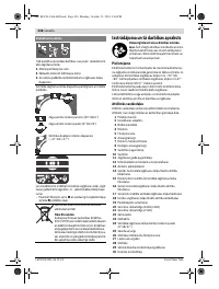
- 282 Заявление о соответствии; Сборка; Комплект поставки
- 283 Избегайте скопления пыли на рабочем месте.
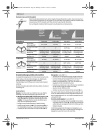
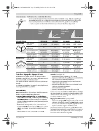
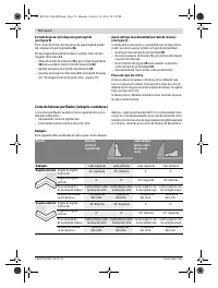
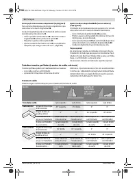
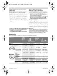
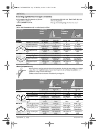
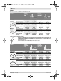
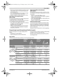
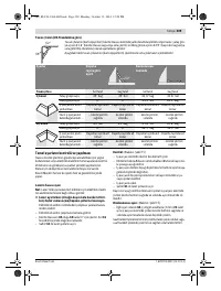
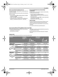
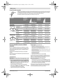
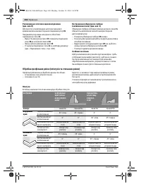
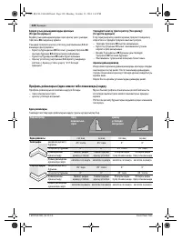
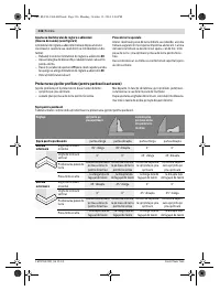
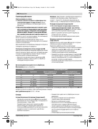
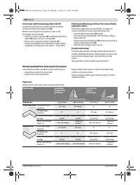
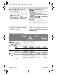
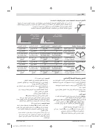
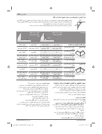
- 284 Работа с инструментом; Фиксация кронштейна; мягкого; более жесткого
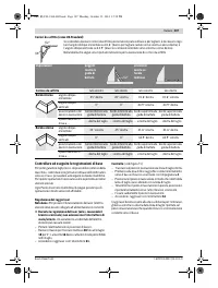
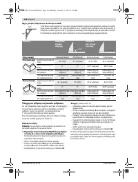
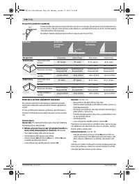
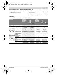
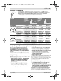
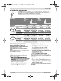
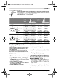
- 285 Настройка горизонтального угла распила; Стандартный угол распила 0 °
- 286 Включение электроинструмента
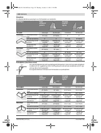
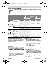
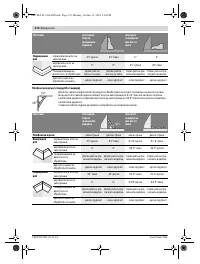
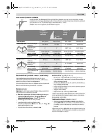
- 287 Минимальные; Пиление; Специальные заготовки
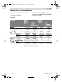
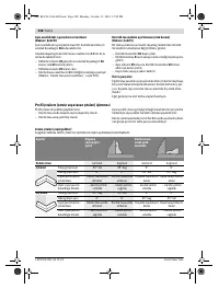
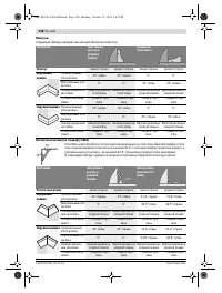
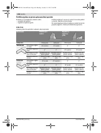
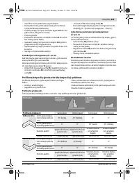
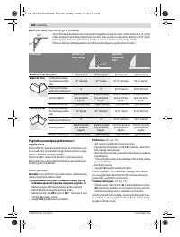
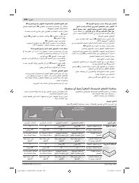
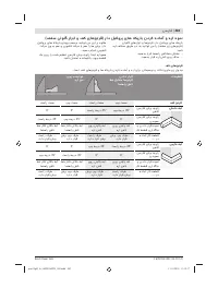
- 288 Плинтусы
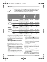
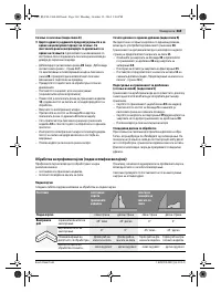
- 289 Основные настройки – контроль и коррекция; Настройка ровности
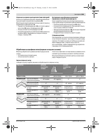
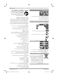
- 291 Техобслуживание и сервис; Техобслуживание и очистка; Очистка; Принадлежности; Пильные диски для пластмассы и цветных металлов
- 292 Россия; Утилизация


