Электропилы Bosch GCM 12 GDL - инструкция пользователя по применению, эксплуатации и установке на русском языке. Мы надеемся, она поможет вам решить возникшие у вас вопросы при эксплуатации техники.
Если остались вопросы, задайте их в комментариях после инструкции.
"Загружаем инструкцию", означает, что нужно подождать пока файл загрузится и можно будет его читать онлайн. Некоторые инструкции очень большие и время их появления зависит от вашей скорости интернета.


English |
39
Bosch Power Tools
1 609 92A 0XN | (13.10.14)
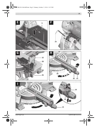
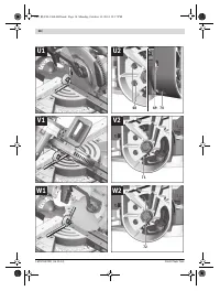
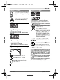
Removing the Adjustable Fence (see figure E)
For extreme bevel angles, the fence extensions
9
must be re-
moved completely.
– Pivot cover plate
53
outward.
– Turn clamping lever
52
toward the front.
– Pull the fence extension
9
completely outward.
– Remove the fence extension upward.
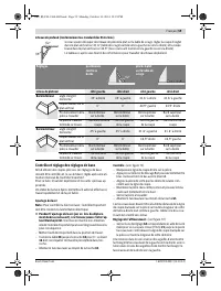
Adjusting the Glide Movement (see figure F)
The glide mechanism of glide arm
28
is factory-preset, and
not set to glide movement upon delivery of the power tool.
The glide movement of the glide movement controller can be
individually adjusted on the controller
54
:
Hard – for more controlled work motion;
Soft – for fast saw cuts.
– For
softer
damping, loosen both set screws
55
using the
hex key (4 mm)
20
or
tighten both set screws
55
for
harder
damping.
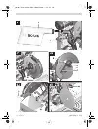
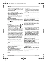
Clamping the Workpiece (see figure G)
To ensure optimum working safety, the workpiece must al-
ways be firmly clamped.
Do not saw workpieces that are too small to clamp.
– Press the workpiece firmly against the fence
10
.
– Insert the material clamp
22
provided into one of the holes
56
intended for it.
– Loosen the wing bolt
57
and adapt the material clamp to
the workpiece. Tighten the wing bolt again.
– Firmly clamp the workpiece by turning the threaded rod
58
in clockwise direction.
Adjusting Mitre Angles
To ensure precise cuts, the basic adjustment of the machine
must be checked and adjusted as necessary after intensive use
(see “Checking and Adjusting the Basic Adjustment”,
page 43).
Always tighten the locking knob 15 firmly before saw-
ing.
Otherwise the saw blade can become wedged in the
workpiece.
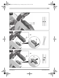
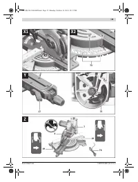
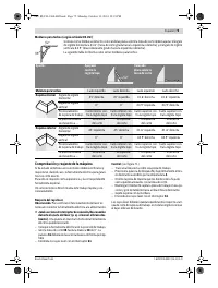
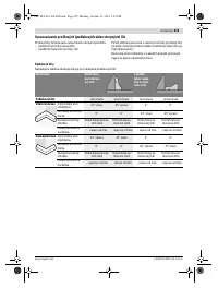
Adjusting Standard Mitre Angles (see figure H)
For quick and precise adjustment of commonly used mitre an-
gles, detents
18
have been provided for on the saw table:
– Loosen the locking knob
15
in case it is tightened.
– Pull lever
16
and rotate the saw table
38
left or right to the
requested detent.
– Release the lever again. The lever must be felt to engage in
the detent.
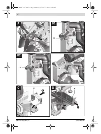
Adjusting Any Mitre Angle (see figure I)
The mitre angle can be set in the range from 52 ° (left side) to
60 ° (right side).
– Loosen the locking knob
15
in case it is tightened.
– Pull lever
16
and at the same time, push mitre detent over-
ride
14
down at the front.
This locks lever
16
and the saw table can move freely.
– Turn the saw table
38
left or right by the locking knob until
the angle indicator
59
indicates the requested mitre angle.
– Tighten the locking knob
15
again.
– To loosen the lever
16
again (for adjusting standard mitre
angles), pull the lever upward.
The mitre detent override
14
snaps back to its original po-
sition and lever
16
can re-engage into the detents
18
.
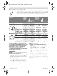
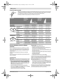
Adjusting Bevel Angles
To ensure precise cuts, the basic adjustment of the machine
must be checked and adjusted as necessary after intensive
use (see “Checking and Adjusting the Basic Adjustment”,
page 43).
The vertical bevel angle can be adjusted in a range from 47 °
(leftward) to 47 ° (rightward).
For quick and precise setting of frequently used bevel angles,
stops have been provided for the angles 0 °, 22.5 °, 45 ° and
47 °.
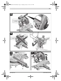
Adjusting the Left-hand Bevel Angle Range
(45 ° to 0 °)
– Pull the left fence extension
9
completely outward (see
“Extending the Fence”, page 38).
– Loosen the lock lever
17
.
– Tilt the glide arm via handle
4
leftward until the angle indi-
cator
33
indicates the desired bevel angle.
– Hold the glide arm in this position and tighten lock lever
17
again.
The clamping force of the lock lever must securely hold the
position of the glide arm at any bevel angle.
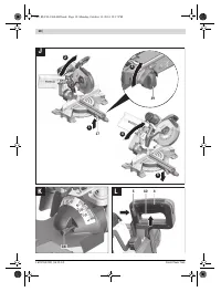
Adjusting the Righthand Bevel Angle Range
(0 ° to 45 °) (see figure J)
– Pull the right fence extension
9
completely out-
ward (see “Extending the Fence”, page 38).
– Loosen the lock lever
17
.
– Lightly tilt the glide arm leftward out of the 0 °position via
handle
4
and turn rotary knob
39
until the desired bevel
angle range is indicated.
– Tilt the glide arm via handle
4
to the right until angle indica-
tor
24
indicates the desired bevel angle.
– Hold the glide arm in this position and tighten lock lever
17
again.
The clamping force of the lock lever must securely hold the
position of the glide arm at any bevel angle.
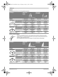
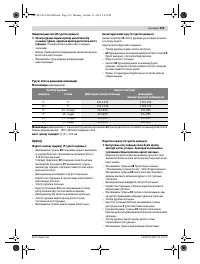
Standard 0 ° Bevel Angle
To enable simple and swift resetting of the standard 0 °
bevel angle, rotary knob
39
will engage in the bevel angle
range .
– Tilt the glide arm from right to left over the 0 ° position.
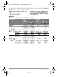
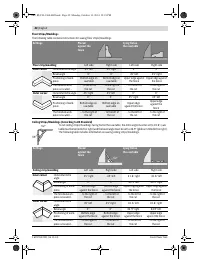
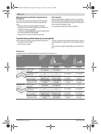
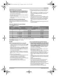
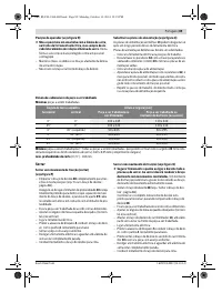
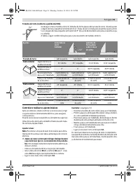
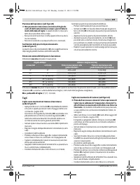
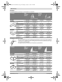
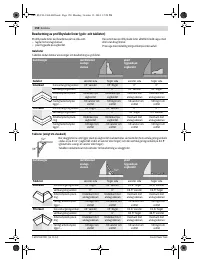
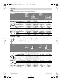
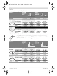
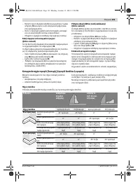
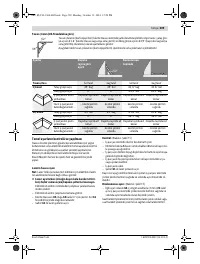
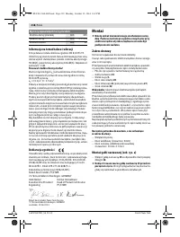
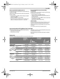
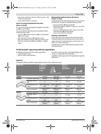
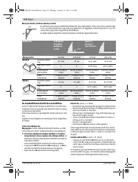
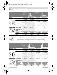
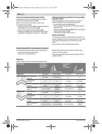
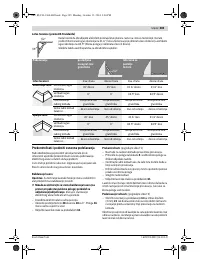
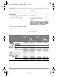
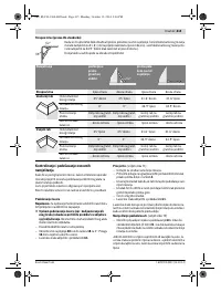
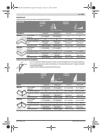
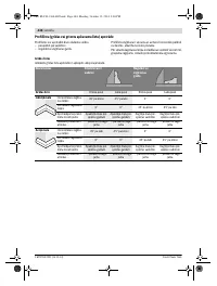
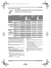
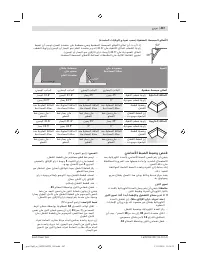
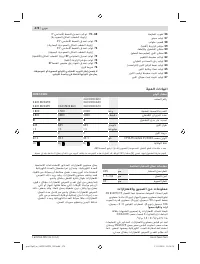
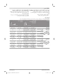
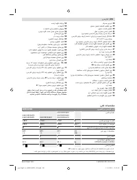
Left
Right
0 °
15 °; 22.5 °; 31.6 °; 45 °
15 °; 22.5 °; 31.6 °; 45 °; 60 °
OBJ_BUCH-1360-002.book Page 39 Monday, October 13, 2014 12:18 PM
Содержание
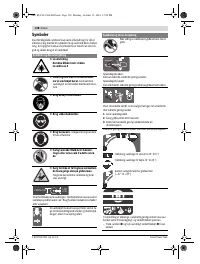
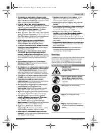
- 277 Защищайте электроинструмент от дождя и сырости.
- 278 Держите Ваше рабочее место в чистоте.
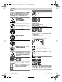
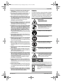
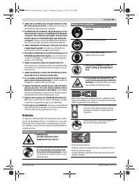
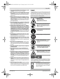
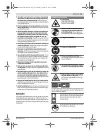
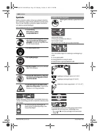
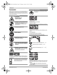
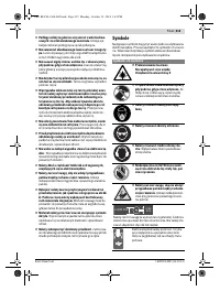
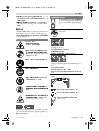
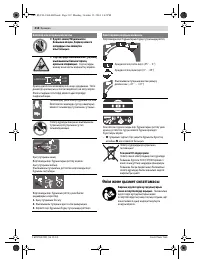
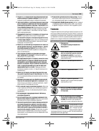
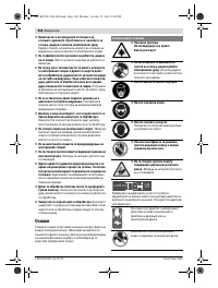
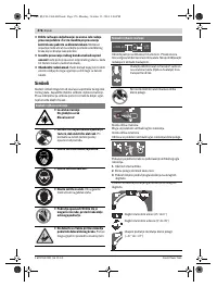
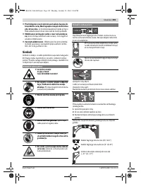
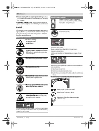
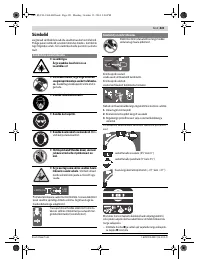
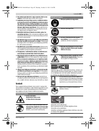
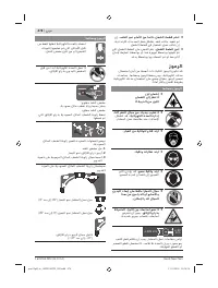
- 279 Закрепляйте заготовку.; Символы; Символы и их значение
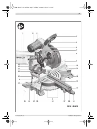
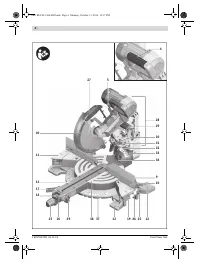
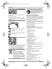
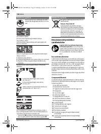
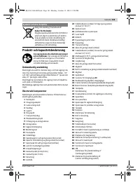
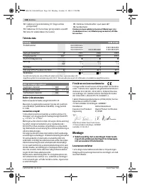
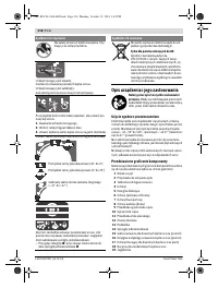
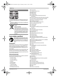
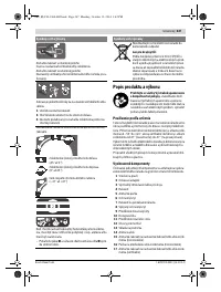
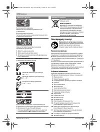
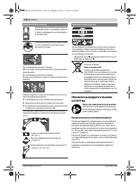
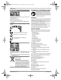
- 280 Описание продукта и услуг; Применение по назначению
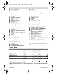
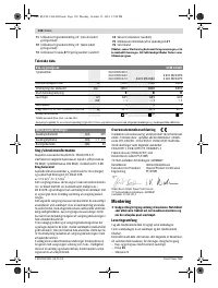
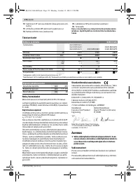
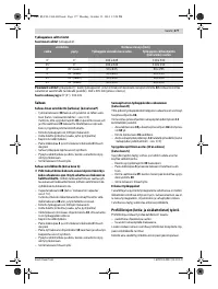
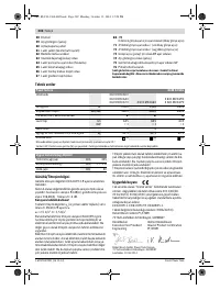
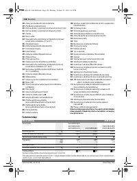
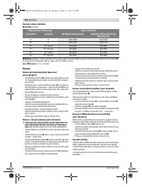
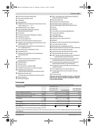
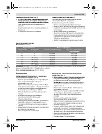
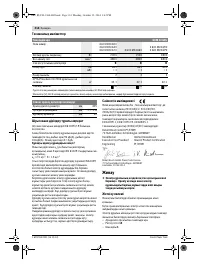
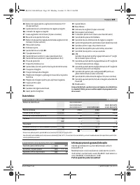
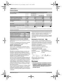
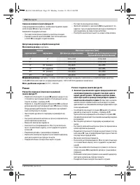
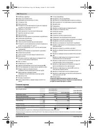
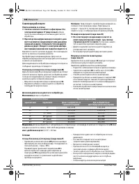
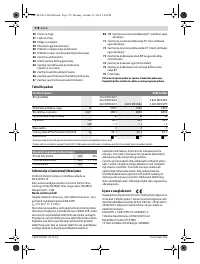
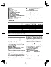
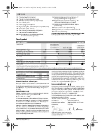
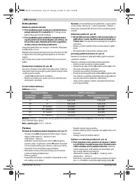
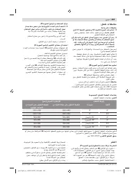
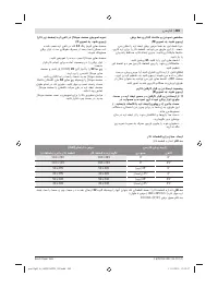
- 281 Технические данные; Применяйте средства защиты органов слуха!; Размеры пильных дисков
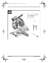
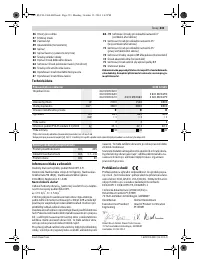
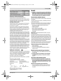
- 282 Заявление о соответствии; Сборка; Комплект поставки
- 283 Избегайте скопления пыли на рабочем месте.
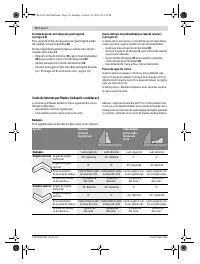
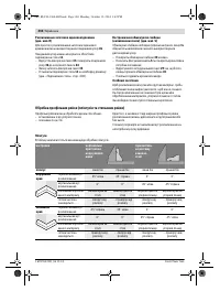
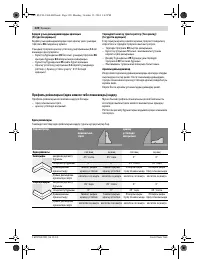
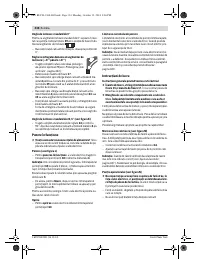
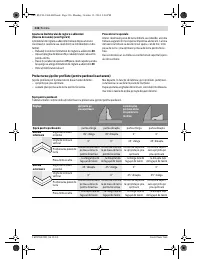
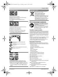
- 284 Работа с инструментом; Фиксация кронштейна; мягкого; более жесткого
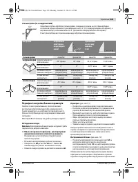
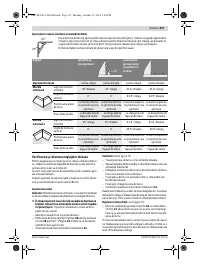
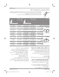
- 285 Настройка горизонтального угла распила; Стандартный угол распила 0 °
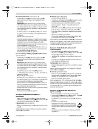
- 286 Включение электроинструмента
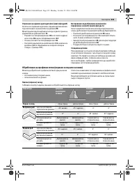
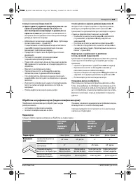
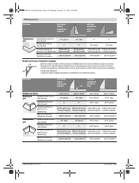
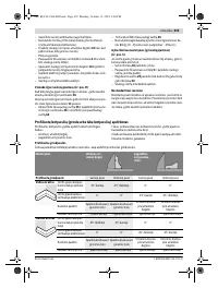
- 287 Минимальные; Пиление; Специальные заготовки
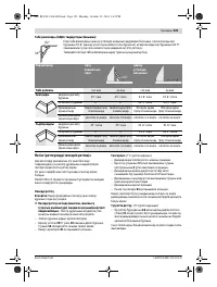
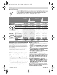
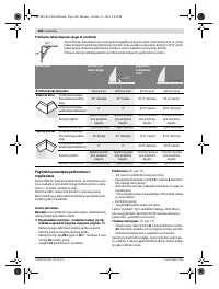
- 288 Плинтусы
- 289 Основные настройки – контроль и коррекция; Настройка ровности
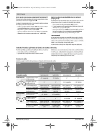
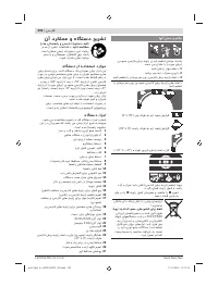
- 291 Техобслуживание и сервис; Техобслуживание и очистка; Очистка; Принадлежности; Пильные диски для пластмассы и цветных металлов
- 292 Россия; Утилизация


