
Котел De Dietrich MS 24 BIC FF - инструкция пользователя по применению, эксплуатации и установке на русском языке. Мы надеемся, она поможет вам решить возникшие у вас вопросы при эксплуатации техники.
Если остались вопросы, задайте их в комментариях после инструкции.
"Загружаем инструкцию", означает, что нужно подождать пока файл загрузится и можно будет его читать онлайн. Некоторые инструкции очень большие и время их появления зависит от вашей скорости интернета.


78
71.06199.02 - EN
INSTALLATION INSTRUCTIONS
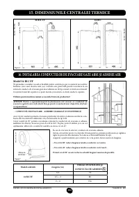
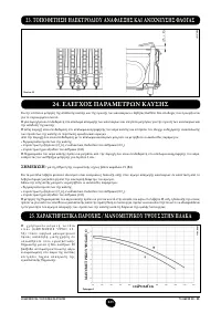
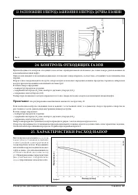
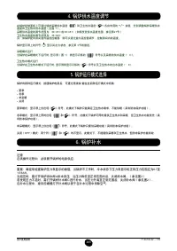
To measure combustion eficiency and the toxicity of the products of combustion, the boiler is itted with two dedicated
test points.
One connection point is connected to the exhaust duct and is used to measure combustion eficiency and the toxicity of
the products of combustion.
The other is connected to the air intake circuit and is used to check for the presence of any products of combustion
circu¬lating in installations with co-axial lues.
The following parameters can be measured using the test point connected to the exhaust duct:
• temperature of the products of combustion;
• concentration of oxygen (O
2
) or, alternatively, carbon dioxide (CO
2
);
• concentration of carbon monoxide (CO).
The temperature of the comburent air must be measured on the test point located on the air intake lue by inserting the
measurement sensor by about 3 cm.
N.B.:
to regulate the rated power, see chapter 19 (B1)
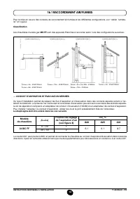
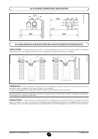
For natural draught boiler models, a hole must be made in the exhaust lue at a distance from the boiler equal to twice
the internal diameter of the lue.
The following parameters can be measured through this hole:
• temperature of the products of combustion;
• concentration of oxygen (O
2
) or, alternatively, carbon dioxide (CO
2
);
• concentration of carbon monoxide (CO).
The temperature of the combustion air must be measured close to the point where the air enters the boiler. The hole,
which must be made by the person in charge of the system during commissioning, must be sealed so as to ensure that
the exhaust duct is airtight during normal operation.
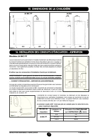
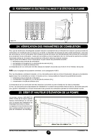
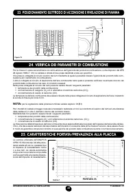
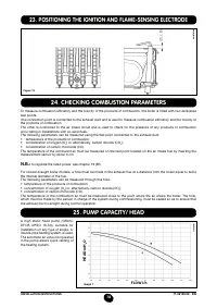
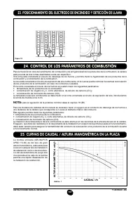
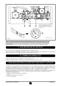
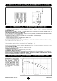
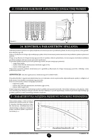
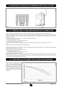
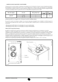
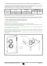
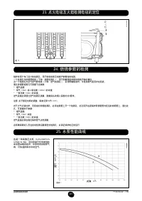
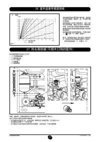
24. CHECKING COMBUSTION PARAMETERS
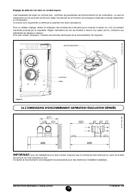
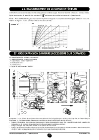
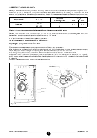
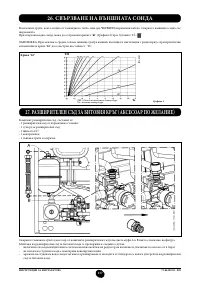
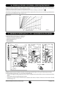
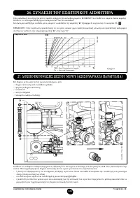
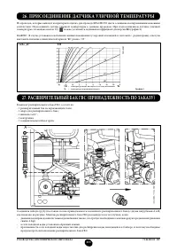
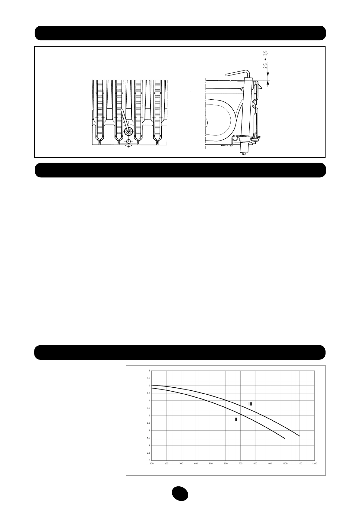
25. PUMP CAPACITY/ HEAD
A high static head pump (GRUN-
DFOS UPSO 15-50), suitable for
installation on any type of single- or
double-pipe heating system, is used.
The automatic air valve incorporated
in the pump allows quick venting of
the heating system.
Graph 1
FLOW l/h
HEAD mH
2
O
1103_0901
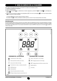
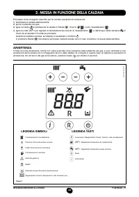
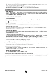
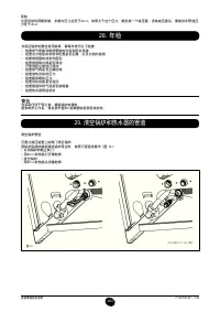
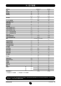
23. POSITIONING THE IGNITION AND FLAME-SENSING ELECTRODE
Figure 13
9912070100
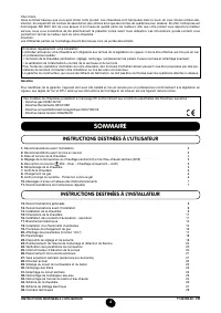
Содержание
- 234 ПОДГОТОВКА К УСТАНОВКЕ; ПОДГОТОВКА К ПЕРВОМУ ПУСКУ
- 235 Внимание
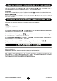
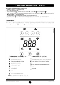
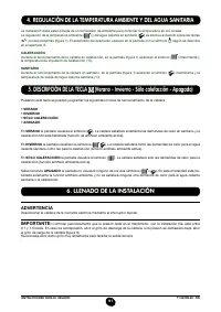
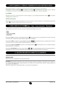
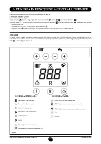
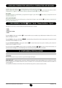
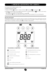
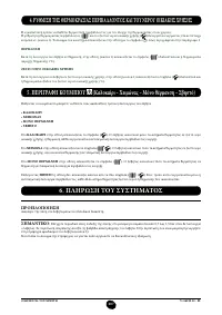
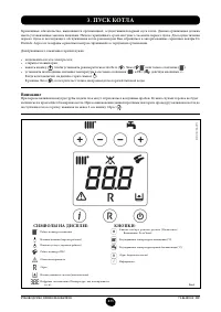
- 236 ОПИСАНИЕ КНОПКИ (Лето – Зима – Только Отопление – Выключено); ЗАПОЛНЕНИЕ СИСТЕМЫ
- 237 ВЫКЛЮЧЕНИЕ КОТЛА; ВЫКЛЮЧЕНИЕ НА ДЛИТЕЛЬНЫЙ ПЕРИОД. ЗАЩИТА ОТ ЗАМЕРЗАНИЯ
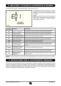
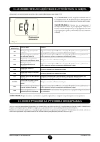
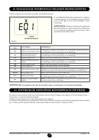
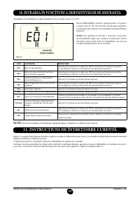
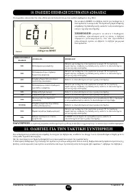
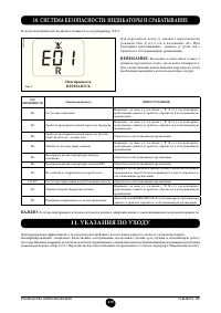
- 238 СИСТЕМА БЕЗОПАСНОСТИ: ИНДИКАТОРЫ И СРАБАТЫВАНИЕ; Неисправность
- 240 ПРОВЕРКИ ПЕРЕД УСТАНОВКОЙ КОТЛА
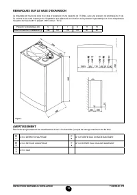
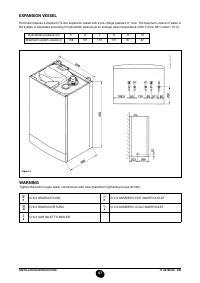
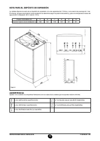
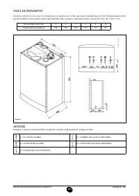
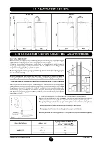
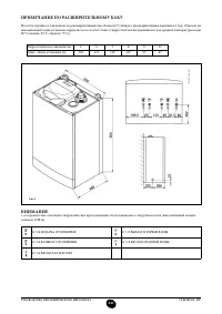
- 241 ПРИМЕЧАНИЕ ПО РАСШИРИТЕЛЬНОМУ БАКУ
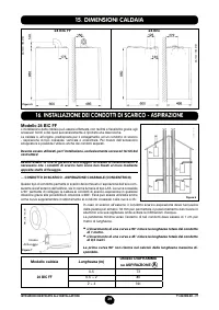
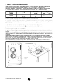
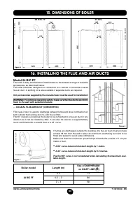
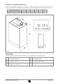
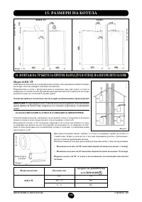
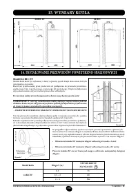
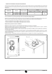
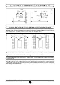
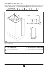
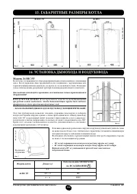
- 242 Модель 24 BIC FF; Модель котла; НЕТ
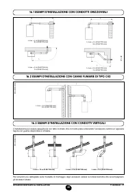
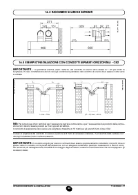
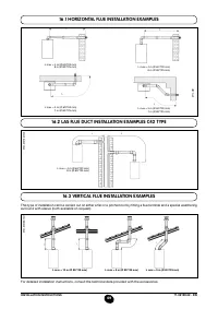
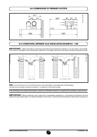
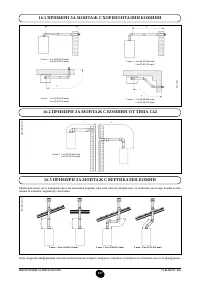
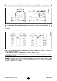
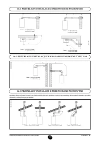
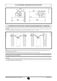
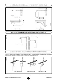
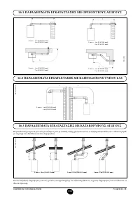
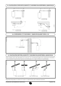
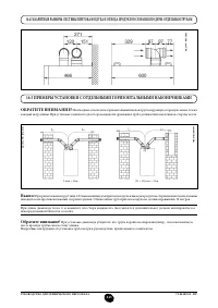
- 243 ВАРИАНТЫ ГОРИЗОНТАЛЬНОЙ УСТАНОВКИ НАКОНЕЧНИКА ДЫМОХОДА
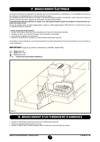
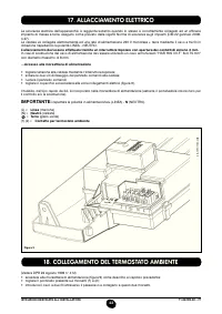
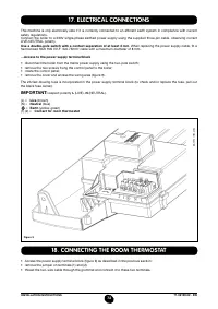
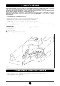
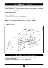
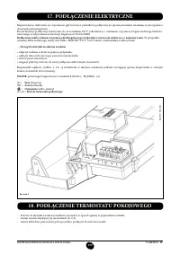
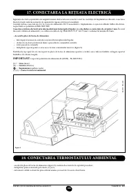
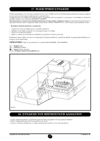
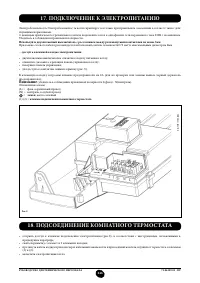
- 246 ПОДКЛЮЧЕНИЕ К ЭЛЕКТРОПИТАНИЮ; ПОДСОЕДИНЕНИЕ КОМНАТНОГО ТЕРМОСТАТА
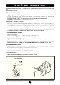
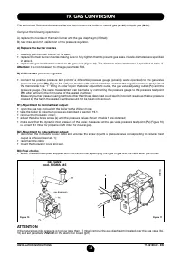
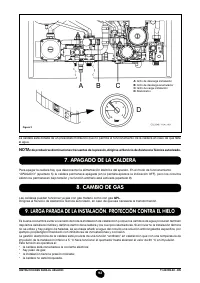
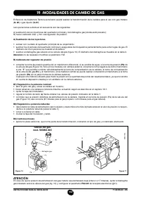
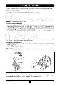
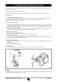
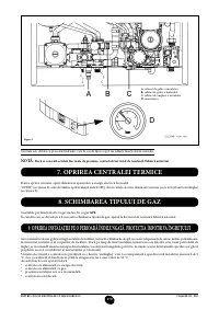
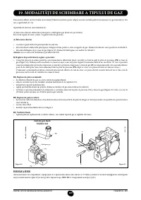
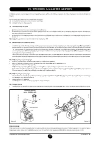
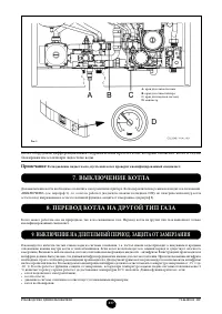
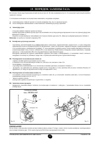
- 247 ПОРЯДОК ЗАМЕНЫ ГАЗА; газовый клапан
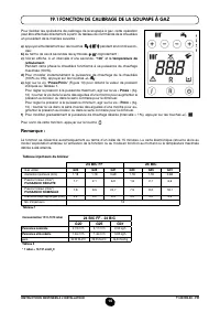
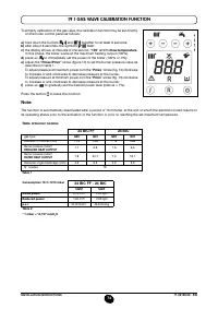
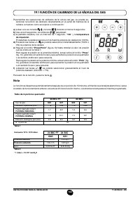
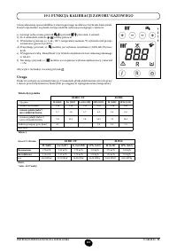
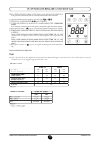
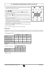
- 248 ФУНКЦИЯ КАЛИБРОВКИ ГАЗОВОГО КЛАПАНА; Примечание
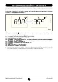
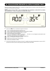
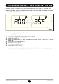
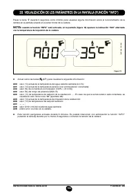
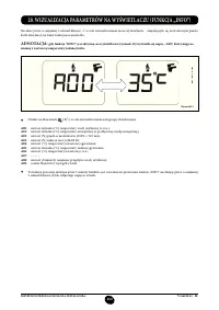
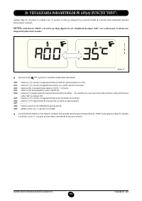
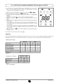
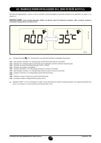
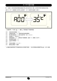
- 249 ВЫВОД ИНФОРМАЦИИ НА ДИСПЛЕЙ КОТЛА
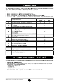
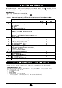
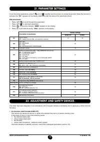
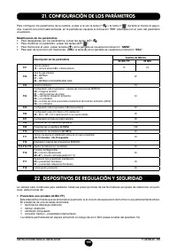
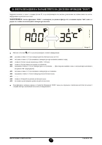
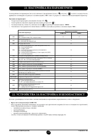
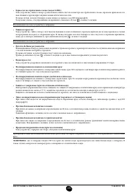
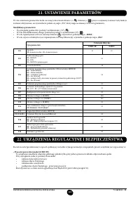
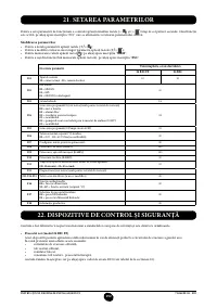
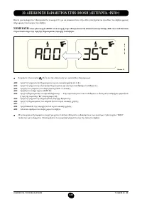
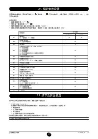
- 250 УСТАНОВКА ПАРАМЕТРОВ; УСТРОЙСТВА РЕГУЛИРОВАНИЯ И ПРЕДОХРАНИТЕЛЬНЫЕ УСТРОЙСТВА
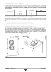
- 252 КОНТРОЛЬ ОТХОДЯЩИХ ГАЗОВ; ап
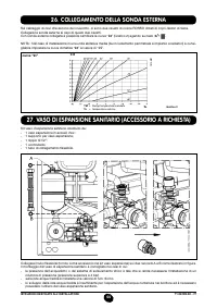
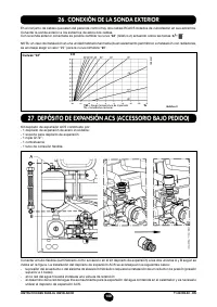
- 253 ПРИСОЕДИНЕНИЕ ДАТЧИКА УЛИЧНОЙ ТЕМПЕРАТУРЫ
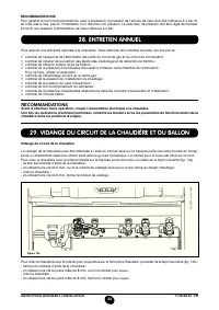
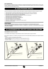
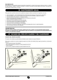
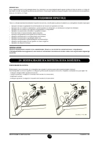
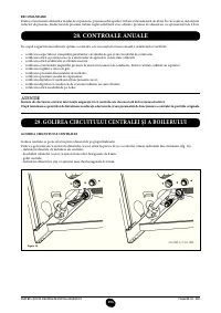
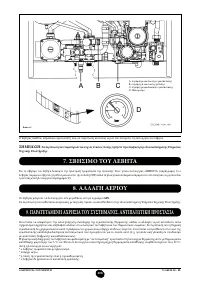
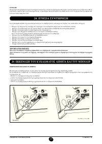
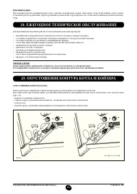
- 254 ЕЖЕГОДНОЕ ТЕХНИЧЕСКОЕ ОБСЛУЖИВАНИЕ; ОПУСТОШЕНИЕ КОНТУРА КОТЛА И БОЙЛЕРА
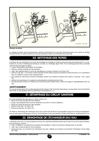
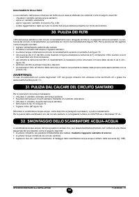
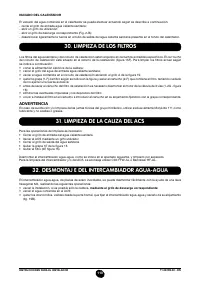
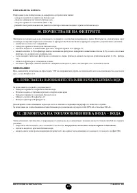
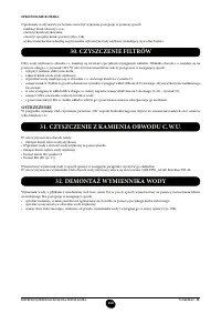
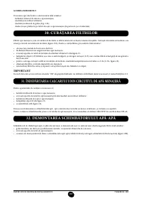
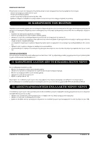
- 255 ОЧИСТКА ОТ ИЗВЕСТКОВОГО НАЛЕТА В СИСТЕМЕ ГВС
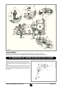
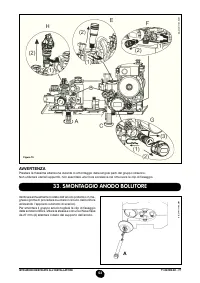
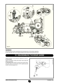
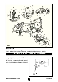
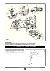
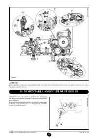
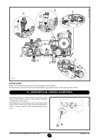
- 256 ДЕМОНТАЖ АНОДА БОЙЛЕРА
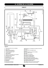
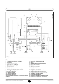
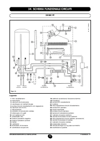
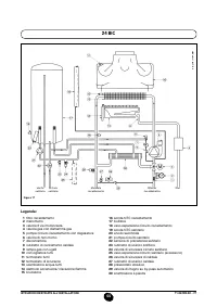
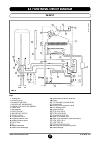
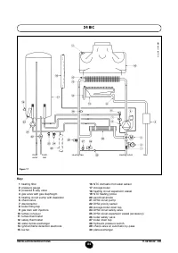
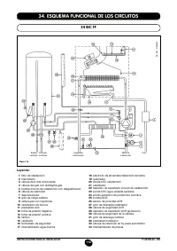
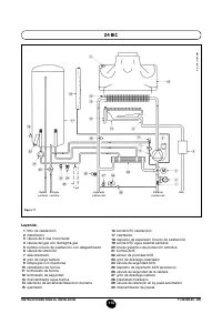
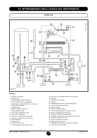
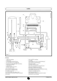
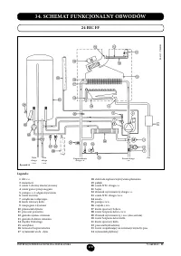
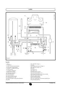
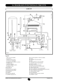
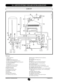
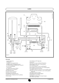
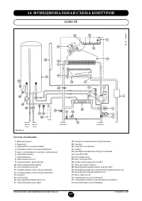
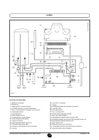
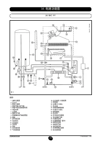
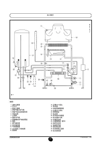
- 257 ФУНКЦИОНАЛЬНАЯ СХЕМА КОНТУРОВ
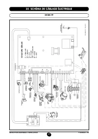
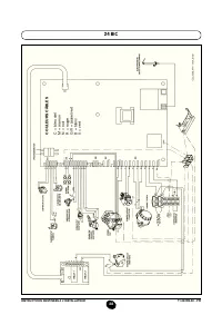
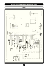
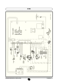
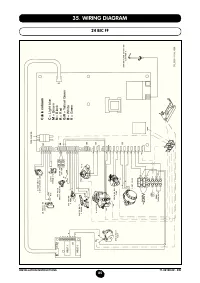
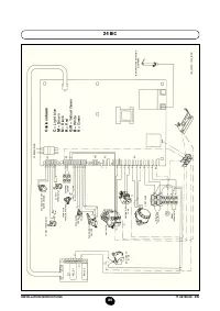
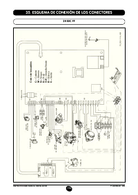
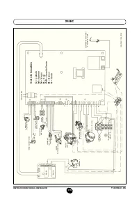
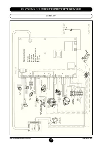
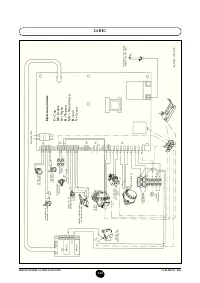
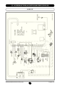
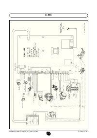
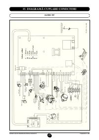
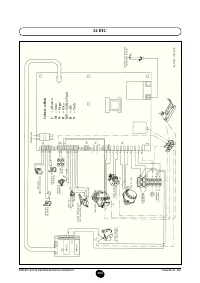
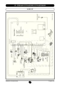
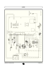
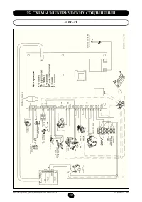
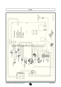
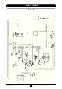
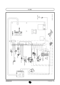
- 259 СХЕМЫ ЭЛЕКТРИЧЕСКИХ СОЕДИНЕНИЙ; Цв
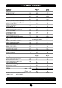
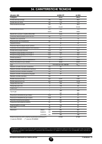
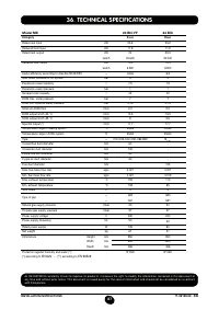
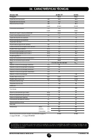
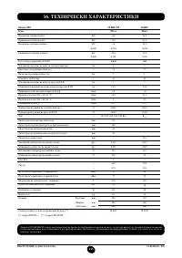
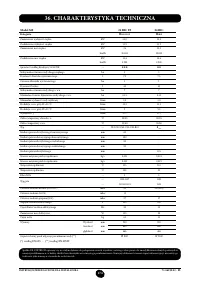
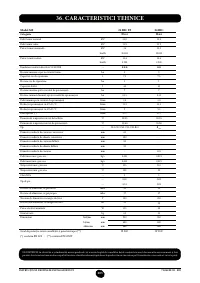
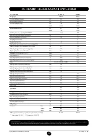
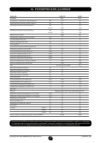
- 261 ТЕХНИЧЕСКИЕ ДАННЫЕ


