
Котел De Dietrich MS 24 BIC FF - инструкция пользователя по применению, эксплуатации и установке на русском языке. Мы надеемся, она поможет вам решить возникшие у вас вопросы при эксплуатации техники.
Если остались вопросы, задайте их в комментариях после инструкции.
"Загружаем инструкцию", означает, что нужно подождать пока файл загрузится и можно будет его читать онлайн. Некоторые инструкции очень большие и время их появления зависит от вашей скорости интернета.


77
71.06199.02 - EN
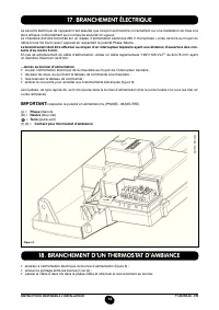
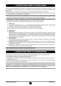
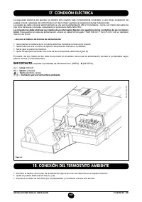
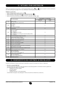
INSTALLATION INSTRUCTIONS
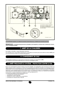
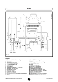
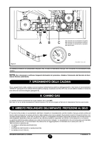
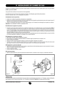
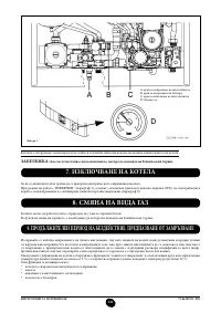
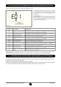
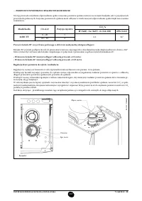
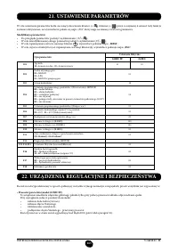
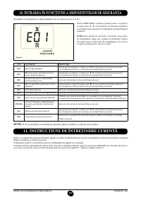
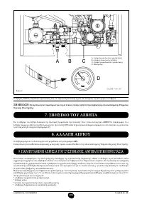
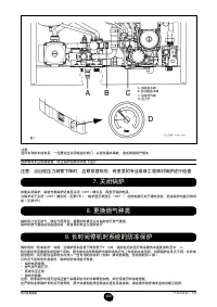
• Fumes thermostat (model 24
BIC)
This device has a sensor positioned on the left section of the fumes hood and shuts off the gas low to the main burner
if the lue is obstructed and/or if there is no draught.
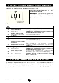
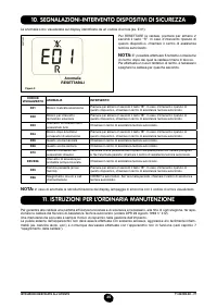
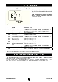
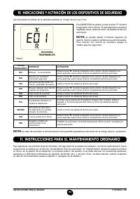
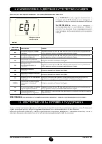
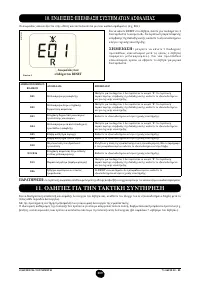
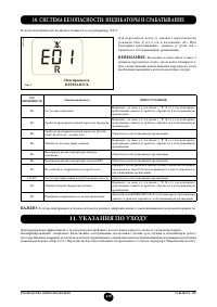
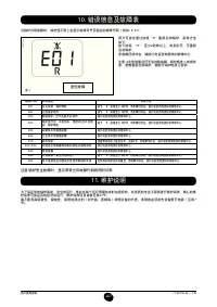
In these conditions the boiler shuts down and displays error code E03 (section 10).
After eliminating the problem, press button ( ), for at least 2 seconds to re-ignite immediately.
It is forbidden to disable this safety device
• Safety thermostat
Thanks to a sensor placed on the CH low line, this thermostat interrupts the low of gas to the burner if the water in
the primary circuit overheats. In these conditions, the boiler is blocked and only after the fault has been eliminated can
it be ignited again by pressing ( ), for at least 2 seconds.
It is forbidden to disenable this safety device
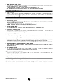
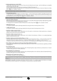
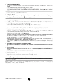
• Flame ionization detector
The lame sensing electrode, located on the right-hand side of the burner, guarantees safety of operation in case of gas
failure or incomplete ignition of the burner.
In these conditions, the boiler is blocked after 3 ignition attempts.
Press ( ), for at least 2 seconds to re-establish normal operating conditions.
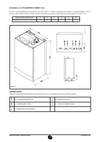
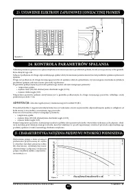
• Hydraulic pressure switch
This device allows the main burner to be ignited only if system pressure is higher than 0.5 bars.
• Pump overrun for heating circuit
The electronically-controlled pump post-circulation function lasts 180 seconds and is enabled, in the heating mode, if
the ambient thermostat causes the burner to go out.
• Pump overrun for DHW circuit
The electronically-controlled pump post-circulation function lasts 30 seconds and is enabled, in the DHW mode, if the
probe causes the burner to go out.
• Frost protection device (CH and DHW systems)
The electronic boiler management system includes a “frost protection” function for the heating system which, when
delivery temperature falls below 5°C, operates the burner until a delivery temperature of 30°C is reached.
This function is enabled when the boiler is switched on, the gas supply is open and the system is correctly pressurised.
• Water not circulating in primary circuit (pump probably blocked)
If there is insuficient or no water circulating in the primary circuit, the boiler blocks and the error code E25 is shown on
the display (section 10).
• Anti-block pump function
If no heat demand is received for 24 consecutive hours, in the heating mode, the pump will automatically start and
operate for 10 seconds. This function is operative when the boiler is powered.
• Three-way valve anti-blockage function
If no heat demand is received for a period of 24 hours, the three-way valve performs a complete switching cycle. This
function is operative when the boiler is powered.
• Hydraulic safety valve (heating circuit)
This device is set to 3 bar and is used for the heating circuit
.
Connect the safety valve to a drain trap. Do not use it to drain the heating circuit.
N.B.:
domestic hot water is guaranteed even if the NTC sensor develops a fault. In this case, temperature is controlled
by the delivery sensor.
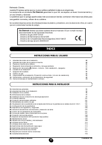
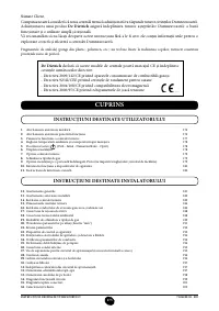
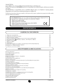
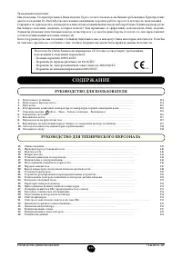
Содержание
- 234 ПОДГОТОВКА К УСТАНОВКЕ; ПОДГОТОВКА К ПЕРВОМУ ПУСКУ
- 235 Внимание
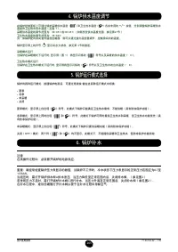
- 236 ОПИСАНИЕ КНОПКИ (Лето – Зима – Только Отопление – Выключено); ЗАПОЛНЕНИЕ СИСТЕМЫ
- 237 ВЫКЛЮЧЕНИЕ КОТЛА; ВЫКЛЮЧЕНИЕ НА ДЛИТЕЛЬНЫЙ ПЕРИОД. ЗАЩИТА ОТ ЗАМЕРЗАНИЯ
- 238 СИСТЕМА БЕЗОПАСНОСТИ: ИНДИКАТОРЫ И СРАБАТЫВАНИЕ; Неисправность
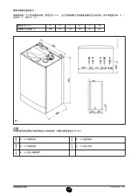
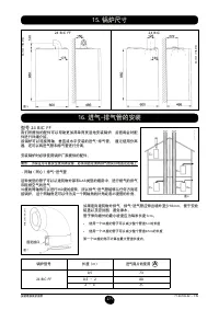
- 240 ПРОВЕРКИ ПЕРЕД УСТАНОВКОЙ КОТЛА
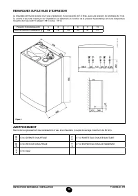
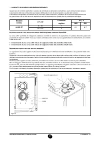
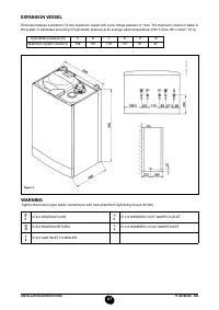
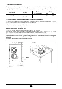
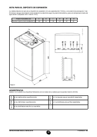
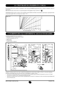
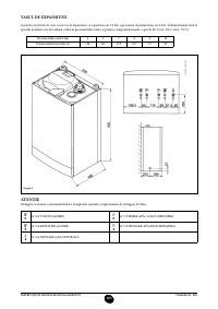
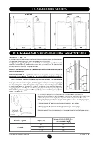
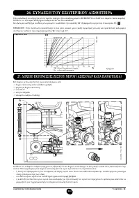
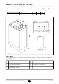
- 241 ПРИМЕЧАНИЕ ПО РАСШИРИТЕЛЬНОМУ БАКУ
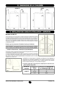
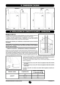
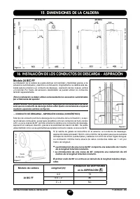
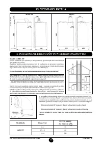
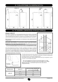
- 242 Модель 24 BIC FF; Модель котла; НЕТ
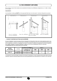
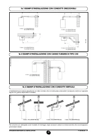
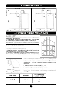
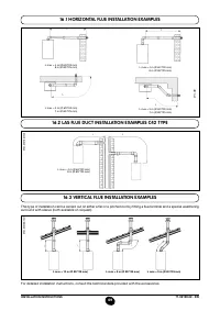
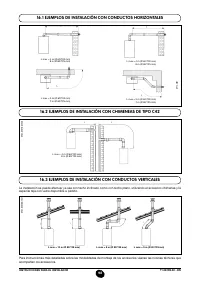
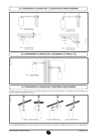
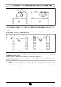
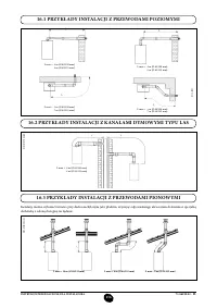
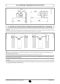
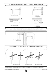
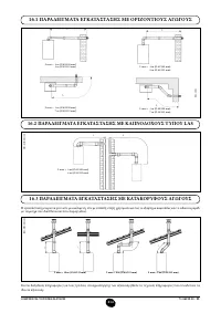
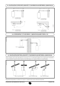
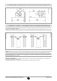
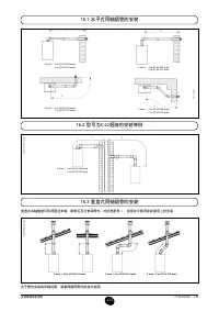
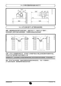
- 243 ВАРИАНТЫ ГОРИЗОНТАЛЬНОЙ УСТАНОВКИ НАКОНЕЧНИКА ДЫМОХОДА
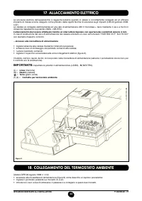
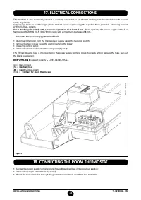
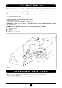
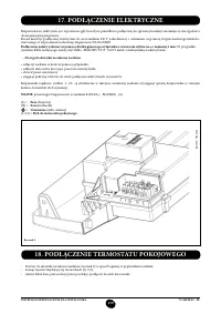
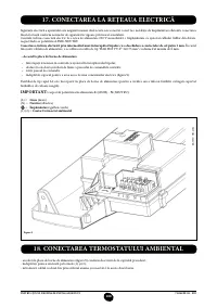
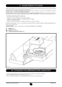
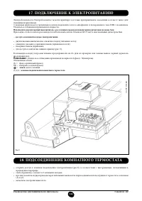
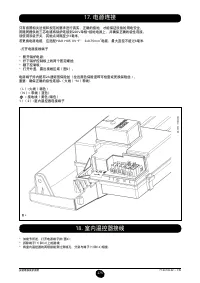
- 246 ПОДКЛЮЧЕНИЕ К ЭЛЕКТРОПИТАНИЮ; ПОДСОЕДИНЕНИЕ КОМНАТНОГО ТЕРМОСТАТА
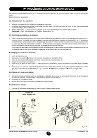
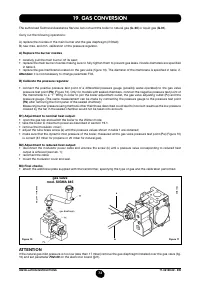
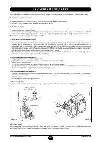
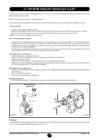
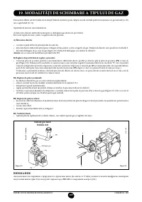
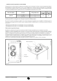
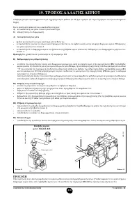
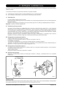
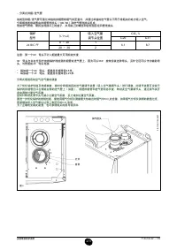
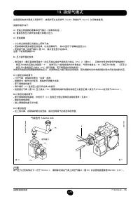
- 247 ПОРЯДОК ЗАМЕНЫ ГАЗА; газовый клапан
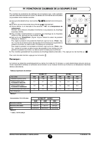
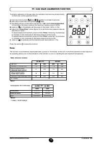
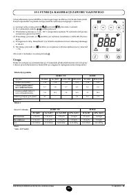
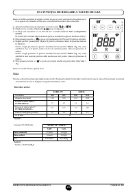
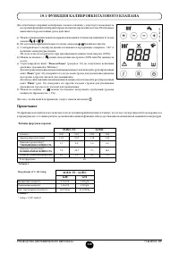
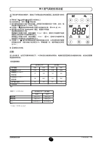
- 248 ФУНКЦИЯ КАЛИБРОВКИ ГАЗОВОГО КЛАПАНА; Примечание
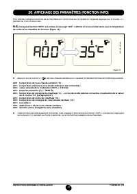
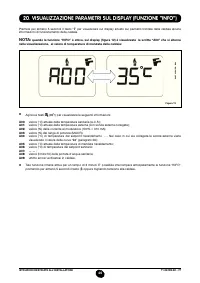
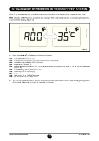
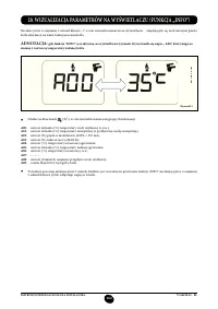
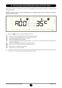
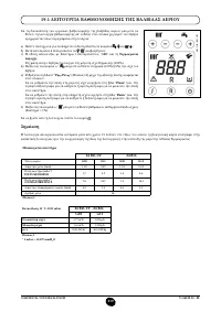
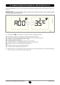
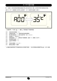
- 249 ВЫВОД ИНФОРМАЦИИ НА ДИСПЛЕЙ КОТЛА
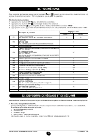
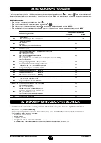
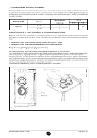
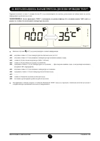
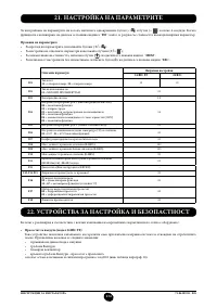
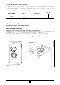
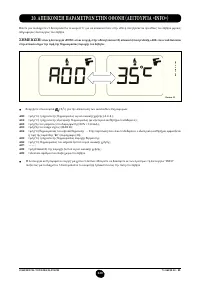
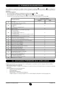
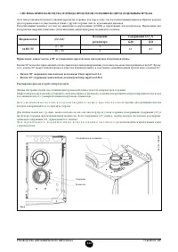
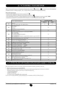
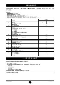
- 250 УСТАНОВКА ПАРАМЕТРОВ; УСТРОЙСТВА РЕГУЛИРОВАНИЯ И ПРЕДОХРАНИТЕЛЬНЫЕ УСТРОЙСТВА
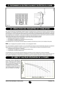
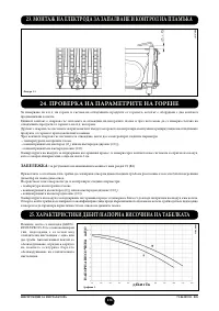
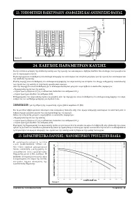
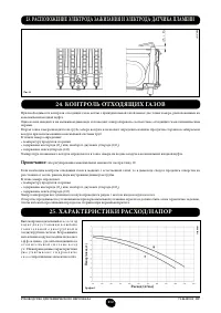
- 252 КОНТРОЛЬ ОТХОДЯЩИХ ГАЗОВ; ап
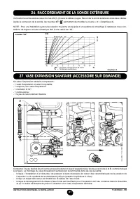
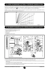
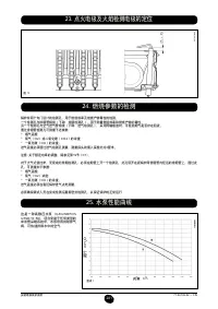
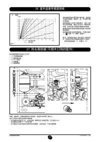
- 253 ПРИСОЕДИНЕНИЕ ДАТЧИКА УЛИЧНОЙ ТЕМПЕРАТУРЫ
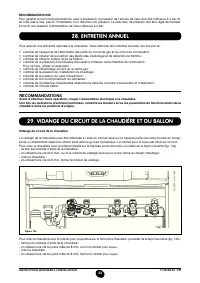
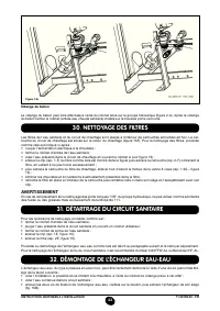
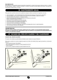
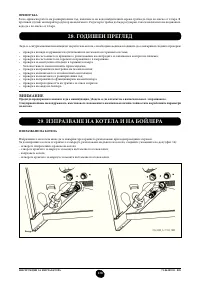
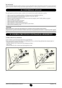
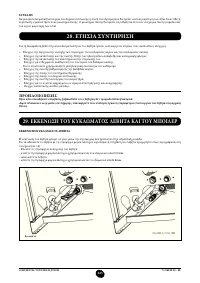
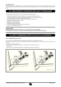
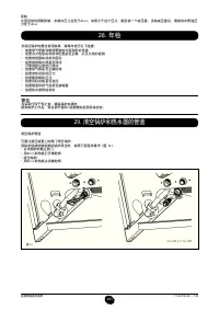
- 254 ЕЖЕГОДНОЕ ТЕХНИЧЕСКОЕ ОБСЛУЖИВАНИЕ; ОПУСТОШЕНИЕ КОНТУРА КОТЛА И БОЙЛЕРА
- 255 ОЧИСТКА ОТ ИЗВЕСТКОВОГО НАЛЕТА В СИСТЕМЕ ГВС
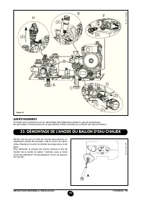
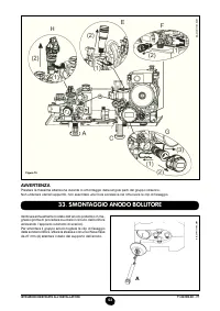
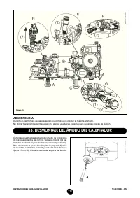
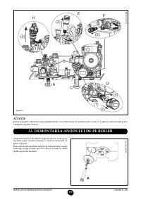
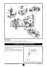
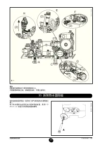
- 256 ДЕМОНТАЖ АНОДА БОЙЛЕРА
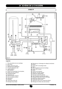
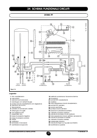
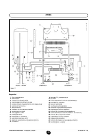
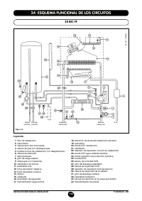
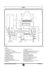
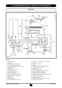
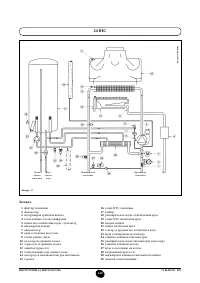
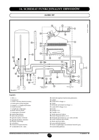
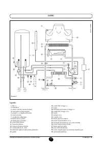
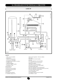
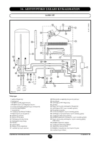
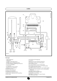
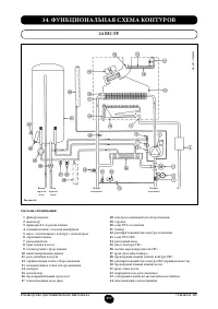
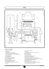
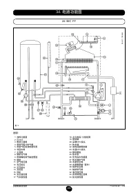
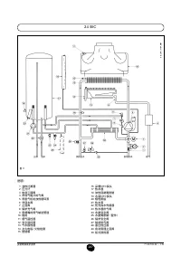
- 257 ФУНКЦИОНАЛЬНАЯ СХЕМА КОНТУРОВ
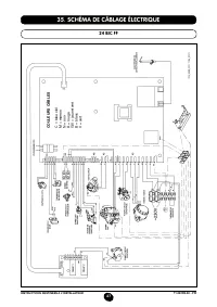
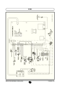
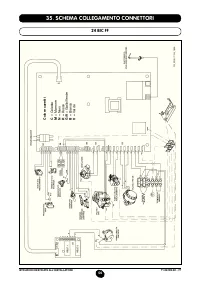
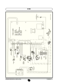
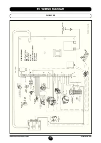
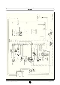
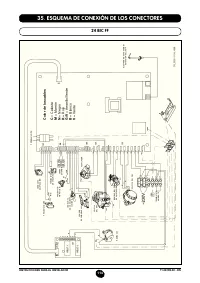
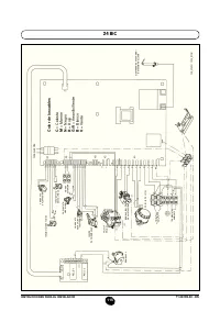
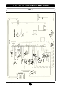
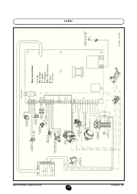
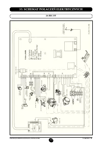
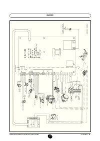
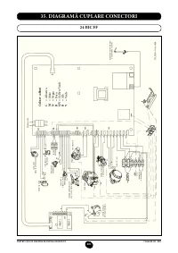
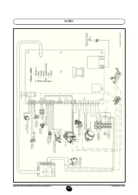
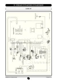
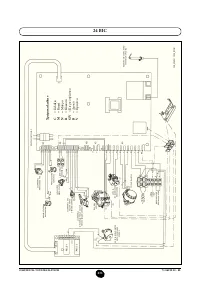
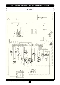
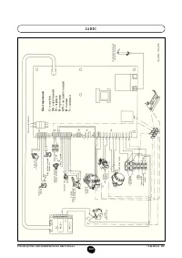
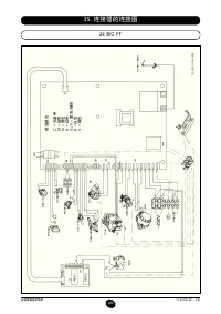
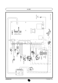
- 259 СХЕМЫ ЭЛЕКТРИЧЕСКИХ СОЕДИНЕНИЙ; Цв
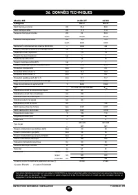
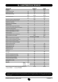
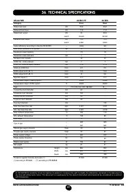
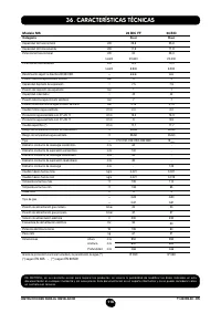
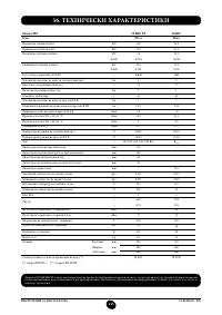
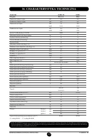
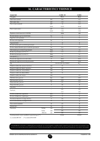
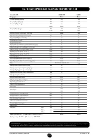
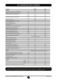
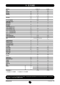
- 261 ТЕХНИЧЕСКИЕ ДАННЫЕ


