
Обогреватели Master B 70CED 4011.819 - инструкция пользователя по применению, эксплуатации и установке на русском языке. Мы надеемся, она поможет вам решить возникшие у вас вопросы при эксплуатации техники.
Если остались вопросы, задайте их в комментариях после инструкции.
"Загружаем инструкцию", означает, что нужно подождать пока файл загрузится и можно будет его читать онлайн. Некоторые инструкции очень большие и время их появления зависит от вашей скорости интернета.


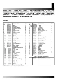
4
GB
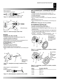
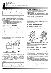
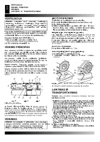
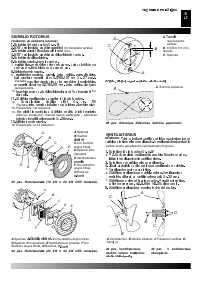
VENTILATION
WARNING: Follow the minimum fresh, outside air
ventilation requirements. If proper fresh, outside air
ventilation is not provided, carbon monoxide poisoning
can occur. Provide proper fresh, outside air ventilation
before running heater.
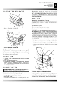
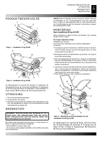
Provide a fresh air opening of at least 2800 square cm (three
square feet) for each 30kw (100,000 Btu/Hr) rating. Provide
extra fresh air if more heaters are being used..
Example: A 43kw (150,000 Btu/Hr) heater requires one of the
following:
• a two-car garage door [4.9 meter (16 feet) opening] raised 9
cm (3.5 inches).
• a single-car garage door [2.75 meter (9 feet) opening] raised
15.25 cm (6 inches).
• two, 76 cm (30 inch) windows raised 28 cm (11 inches).
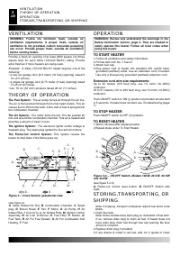
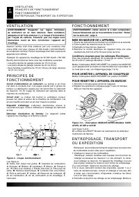
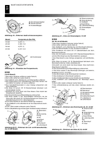
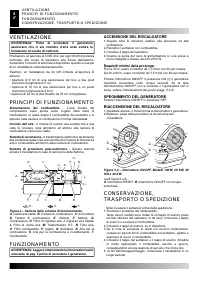
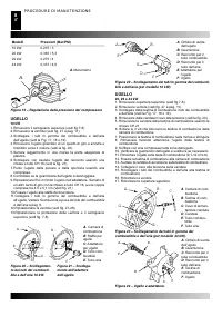
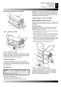
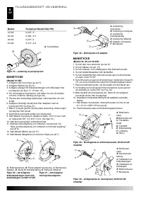
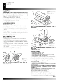
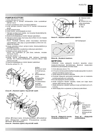
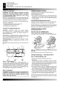
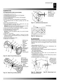
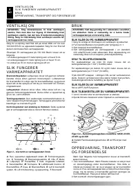
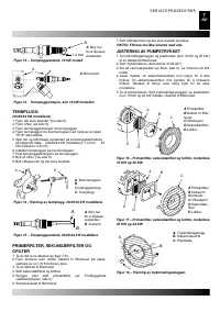
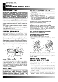
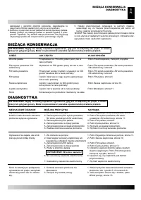
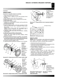
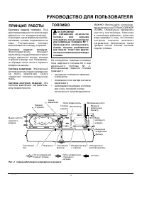
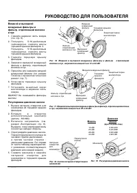
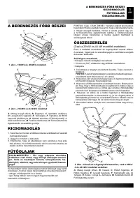
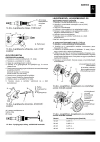
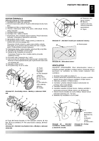
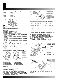
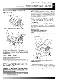
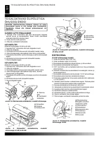
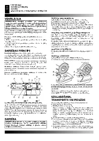
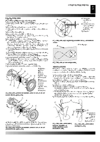
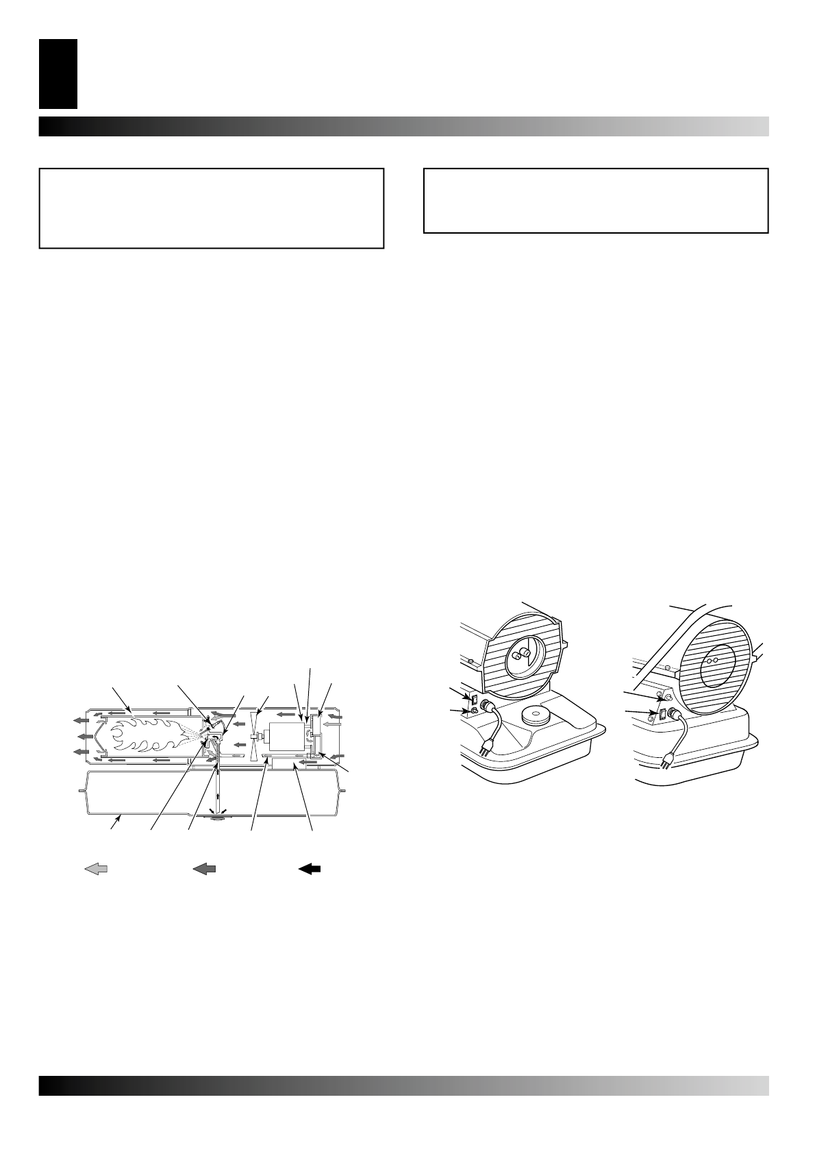
THEORY OF OPERATION
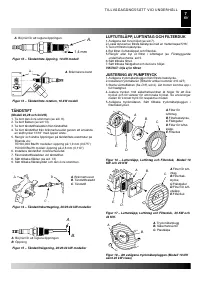
The Fuel System:
The air pump forces air through the air line.
The air is then pushed through the burner head nozzle. This air
causes fuel to lift from the tank. A
fi
ne mist of fuel is sprayed into
the combustion chamber.
The Air System:
The motor turns the fan. The fan pushes air
into and around the combustion chamber. This air is heated and
provides a stream of clean, hot air.
The Ignition System:
The electronic ignitor sends voltage to
thespark plug. The spark plug ignites the fuel and air mixture.
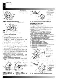
The Flame-Out Control System:
This system causes the
heater to shut down if the
fl
ame goes out.
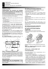
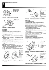
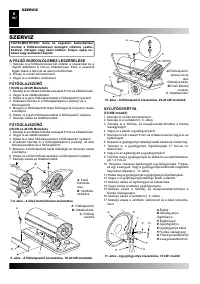
(see
fi
gure 4)
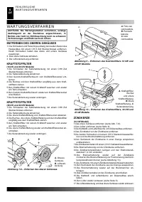
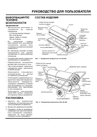
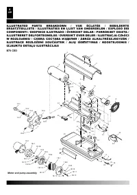
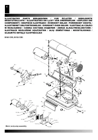
A
. Clean Heated Air Out,
B
. Combustion Chamber,
C
. Spark
plug,
D
. Burner Head,
E
. Fan,
F
. Motor,
G
. Air Pump,
H
. Air
Intake Filter,
I
. Cool Air In,
L
. Air Output Filter,
M
. Ignition Control
Assembly,
N
. Air Line To Burner,
O
. Fuel Filter,
P
. Nozzle,
Q
.
Fuel Tank,
R
. Air For Fuel System,
S
. Air For Combustion And
Heating,
T
. Fuel.
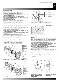
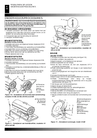
OPERATION
WARNING: Review and understand the warnings in the
Safety Information section, page 2. They are needed to
safely operate this heater. Follow all local codes when
using this heater.
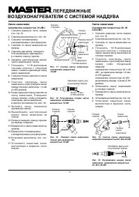
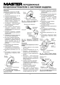
TO START HEATER
1. Follow all ventilation and safety information.
2. Fill fuel tank with No. 1 fuel oil.
3. Attach fuel cap.
4.Plug power cord of heater into standard 230 volt/50 hertz,
grounded (earthed) outlet. Use an extension cord if needed.
Use only a three-prong, grounded (earthed) extension cord.
Extension cord wire size requirements:
Up to 30 meters (100 feet) long, use 1.0 mm2 (16 AWG)
conductor.
30 to 61 meters (101 to 200 feet) long, use1.5 mm2 (14 AWG)
conductor.
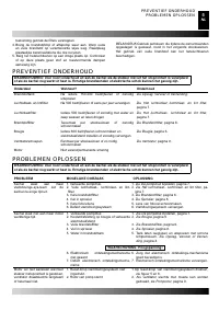
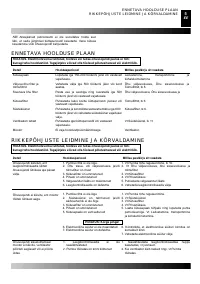
Push ON/OFF switch to ON (|) position and heater should start
in 5 seconds. If heater does not start, see
Troubleshooting
(page
7).
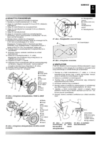
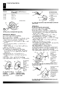
TO STOP HEATER
Push ON/OFF switch to OFF (O) position.
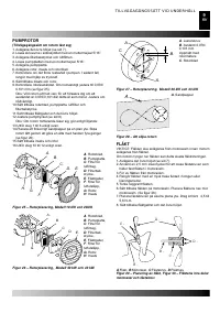
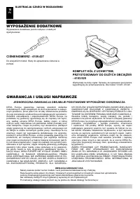
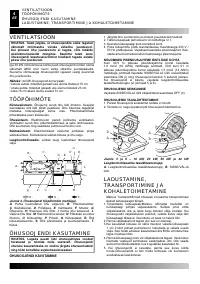
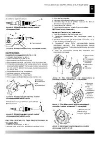
TO RESET HEATER
1. Wait 2 minutes after stopping heater.
2.Repeat steps under
To Start Heater
.
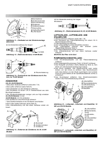
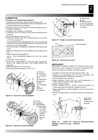
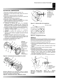
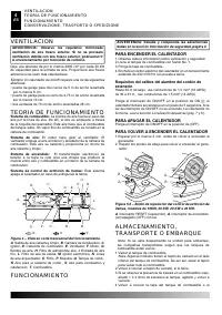
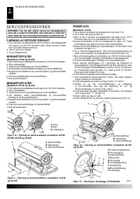
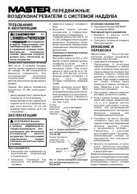
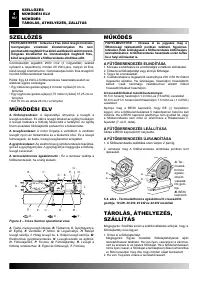
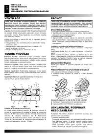
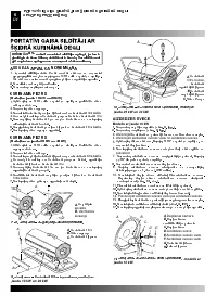
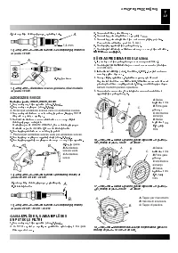
(see
fi
gure 5 e 6)
A.
Flame-out control reset button,
B
. ON/OFF Switch with
Light,
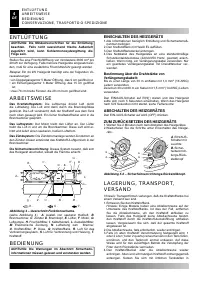
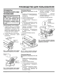
STORING,TRANSPORTING, OR
SHIPPING
Note: If shipping, transport companies require fuel tanks to be
empty.
1. Drain fuel tank.
Note:
Some models have drain plug on underside of fuel tank.
If so, remove drain plug to drain all fuel. If heater does not
have drain plug, drain fuel through fuel cap opening. Be sure
all fuel is removed.
2. Replace drain plug if provided.
3. If any debris is noted in old fuel, add 1or 2 quarts of clean
A .
B .
C .
D . E .
F.
G .
H .
I.
L.
M .
N .
O .
P.
Q .
R .
S .
T.
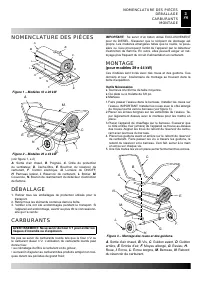
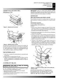
Figure 4 – Cross Section operational view.
A .
B .
A .
B .
Figure 5-6 – ON/OFF Switch, Models 10KW, 20 KW, 30 KW
and 43 KW.
VENTILATION
THEORY OF OPERATION
OPERATION
STORING,TRANSPORTING, OR SHIPPING


