
Обогреватели Master B 70CED 4011.819 - инструкция пользователя по применению, эксплуатации и установке на русском языке. Мы надеемся, она поможет вам решить возникшие у вас вопросы при эксплуатации техники.
Если остались вопросы, задайте их в комментариях после инструкции.
"Загружаем инструкцию", означает, что нужно подождать пока файл загрузится и можно будет его читать онлайн. Некоторые инструкции очень большие и время их появления зависит от вашей скорости интернета.


9
GB
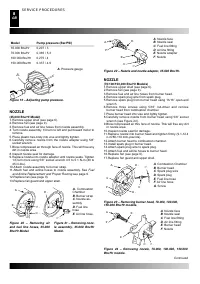
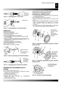
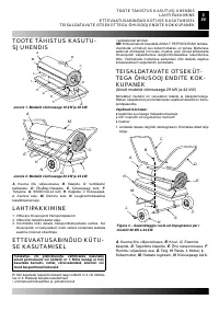
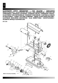
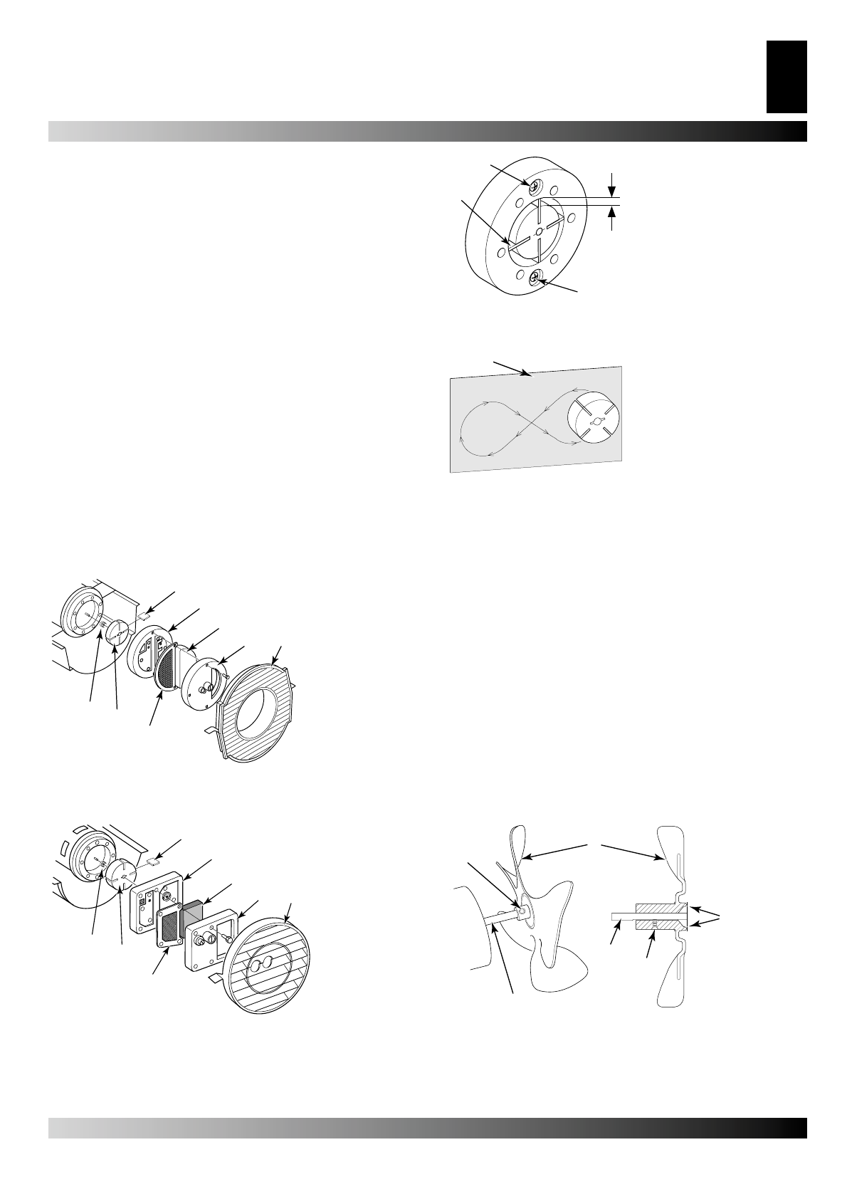
PUMP ROTOR
(Procedure if Rotor is Binding)
1. Remove upper shell (see page 6).
2. Remove
fi
lter end cover screws using5/16” nut-driver.
3. Remove
fi
lter end cover and air
fi
lters.
4.Remove pump plate screws using 5/16”nut-driver.
5. Remove pump plate.
6. Remove rotor, insert, and blades.
7. Check for debris in pump. If debris is found, blow out with
compressed air.
8.Install insert and rotor.
9. Check gap on rotor. Adjust to .076/.101 mm (.003”/.004”) if
needed (see Figure 25).
Note:
Rotate rotor one full turn to ensure the gap is .076/.101
mm (.003”/.004”) at tightest position. Adjust if needed.
10.Install blades, pump plate, air
fi
lters and
fi
lter end cover.
11.Replace fan guard and upper shell.
12.Adjust pump pressure (see page 9).
Note:
If rotor is still binding, proceed as follows.
13.Perform steps 1 through 6 above.
14.Place
fi
ne grade sandpaper (600 grit) on
fl
at surface. Sand
rotor lightly in “
fi
gure 8” motion four times (see Figure 26)
15.Reinstall insert and rotor.
16.Perform steps 10 through 12 above.
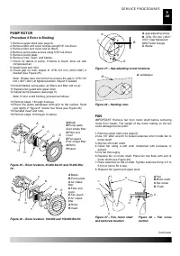
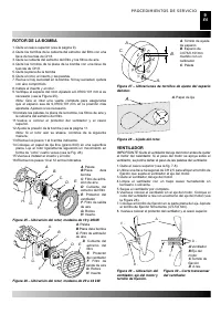
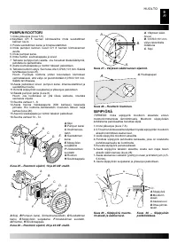
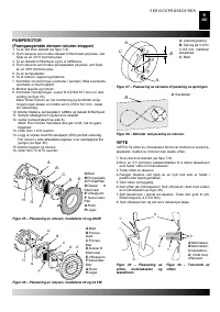
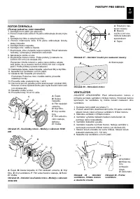
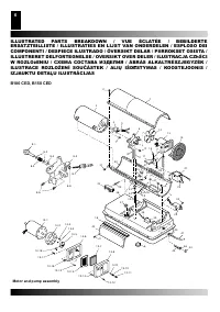
FAN
IMPORTANT:
Remove fan from motor shaft before removing
motor from heater. The weight of the motor resting on the fan
could damage the fan pitch.
1. Remove upper shell (see page 6).
2.Use 1/8” allen wrench to loosen setscrew which holds fan to
motor shaft.
3. Slip fan off motor shaft.
4. Clean fan using a soft cloth moistened with kerosene or
solvent.
5. Dry fan thoroughly.
6. Replace fan on motor shaft. Place fan hub
fl
ush with end of
motor shaft (see Figure 28).
7. Place setscrew on
fl
at of shaft. Tighten setscrew
fi
rmly 4.5 to
5.6 N-m (40 to 50 in-lbs).
8. Replace fan guard and upper shell.
Continued
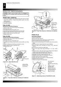
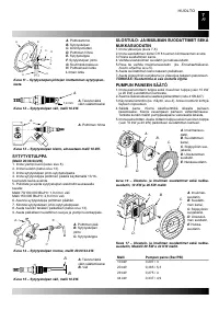
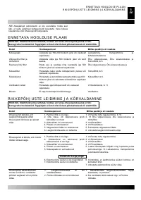
SERVICE PROCEDURES
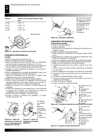
A.
B.
C.
D. E.
F.
G.
H.
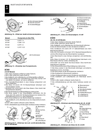
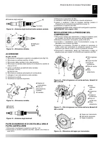
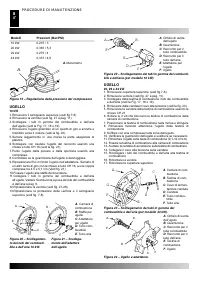
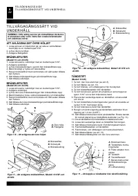
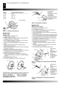
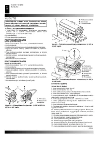
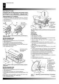
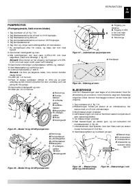
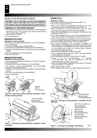
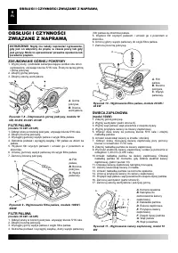
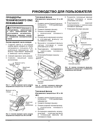
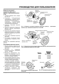
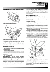
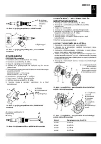
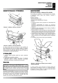
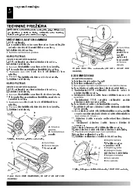
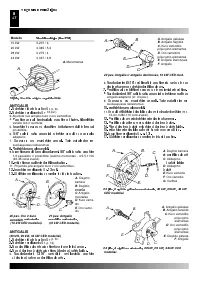
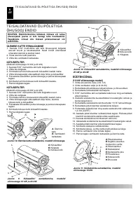
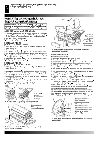
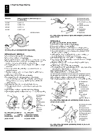
A
.Blade
B
.Pump plate
C
.Air intake
fi
lter
D
.Filter end
cover
E
.Fan guard
F
.Air output
fi
lter
G
.Rotor
H
.Insert.
Figure 25 – Rotor location, 35.000 btu/Hr and 70.000 Btu/
Hr.
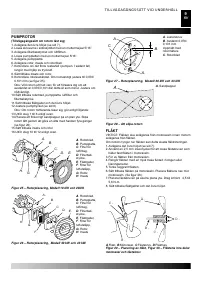
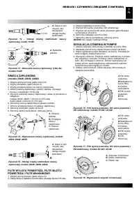
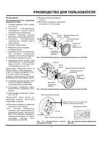
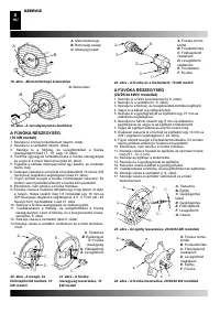
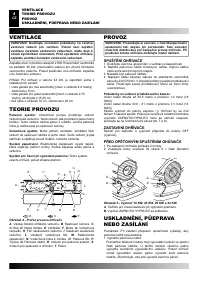
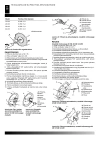
A.
B.
C.
D. E.
F.
G.
H.
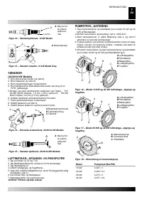
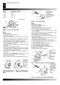
Figure 26 – Rotor location, 100.000 and 150.000 Btu/Hr.
A
.Blade
B
.Pump plate
C
.Air intake
fi
lter
D
.Filter end
cover
E
.Fan guard
F
.Air output
fi
lter
G
.Rotor
H
.Insert.
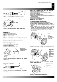
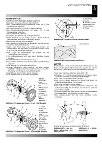
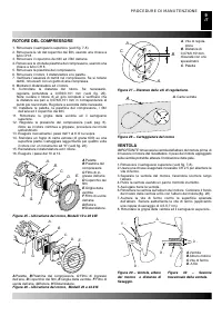
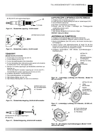
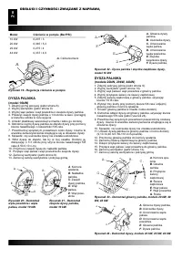
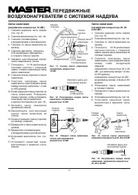
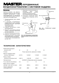
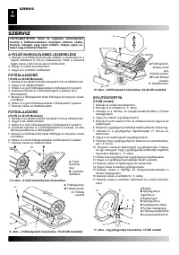
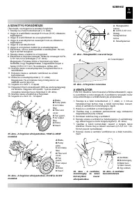
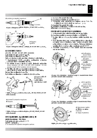
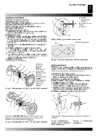
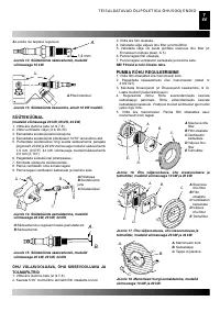
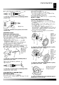
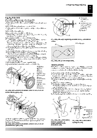
A.
B.
C.
A.
A
. gap adjusting screw
B
. .076/.101 mm (.003”/
.004”) Gap Measured
With Feeler Gauge
C
. Blade
Figure 27 – Gap adjusting screw locations.
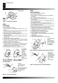
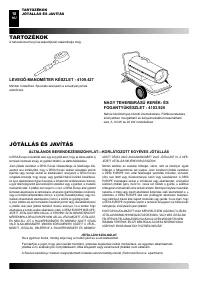
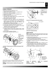
A.
A
. sandpaper
Figure 28 – Sanding rotor.
B .
C .
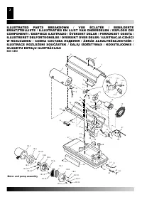
A .
B .
C .
D .
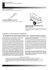
Figure 27 – Fan, motor shaft
and setscrew location.
Figure 28 – Fan cross
section.
A
.Fan
B
.Motor shaft
C
.Set screw
D
. Flush.


