Измерительные приборы Bosch GCL 2-50 - инструкция пользователя по применению, эксплуатации и установке на русском языке. Мы надеемся, она поможет вам решить возникшие у вас вопросы при эксплуатации техники.
Если остались вопросы, задайте их в комментариях после инструкции.
"Загружаем инструкцию", означает, что нужно подождать пока файл загрузится и можно будет его читать онлайн. Некоторые инструкции очень большие и время их появления зависит от вашей скорости интернета.


20
| English
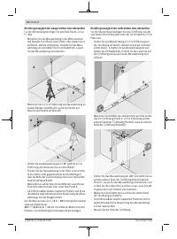
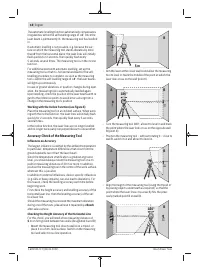
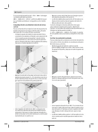
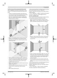
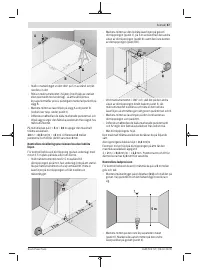
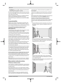
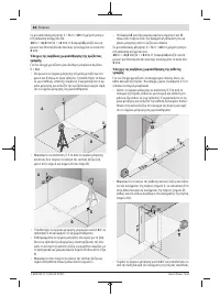
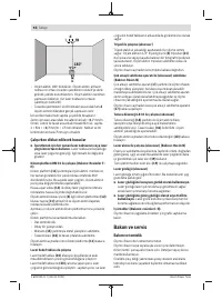
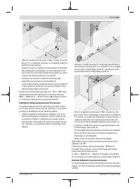
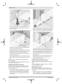
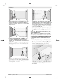
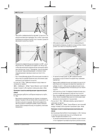
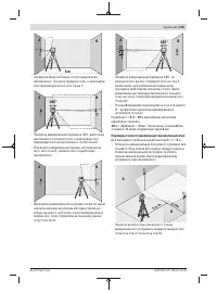
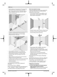
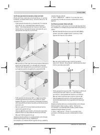
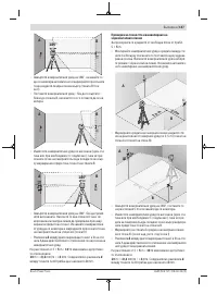
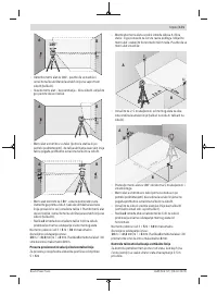
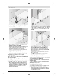
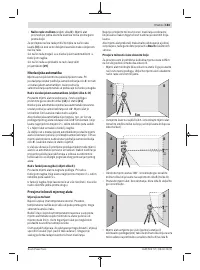
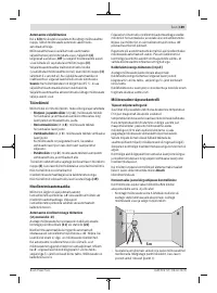
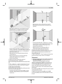
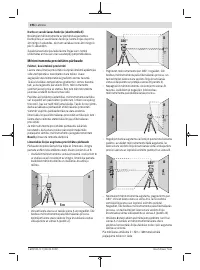
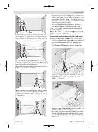
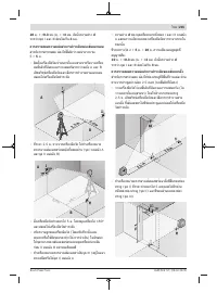
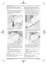
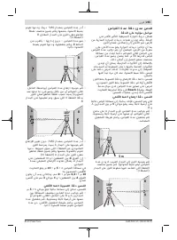
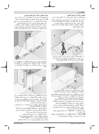
– Rotate the measuring tool 180° and position it on the
other side of the door opening, directly behind point
Ⅱ
.
Allow the measuring tool to level in and align the vertical
laser line in such a way that its centre passes through
points
Ⅰ
and
Ⅱ
exactly.
– Mark the centre of the laser line on the upper edge of the
door opening as point
Ⅳ
.
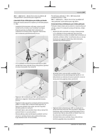
– The discrepancy
d
between the two marked points
Ⅲ
and
Ⅳ
reveals the actual vertical deviation of the measuring
tool.
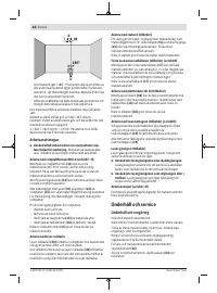
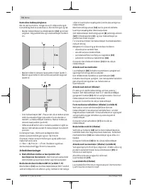
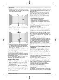
– Measure the height of the door opening.
You can calculate the maximum permitted deviation as fol-
lows:
Doubled height of the door opening ×
0.3
mm/m
Example: At a door opening height of
2
m, the maximum de-
viation amounts to
2 ×
2
m × ±
0.3
mm/m = ±
1.2
mm. The points
Ⅲ
and
Ⅳ
must therefore be no further than
1.2
mm from each other.
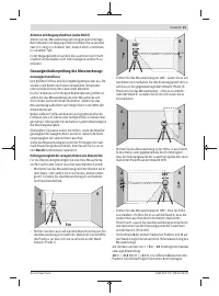
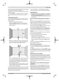
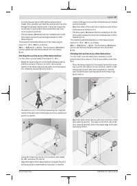
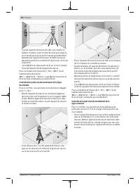
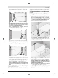
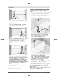
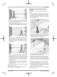
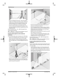
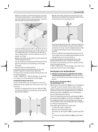
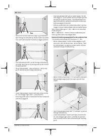
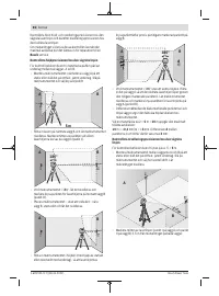
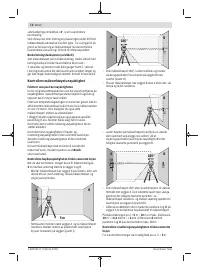
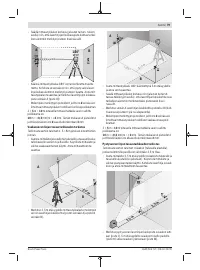
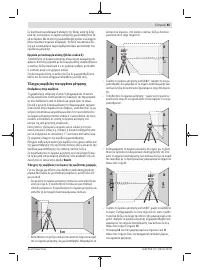
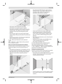
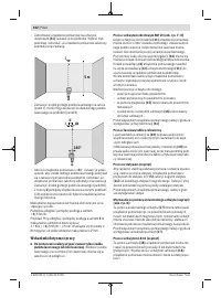
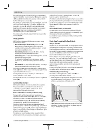
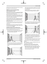
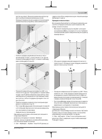
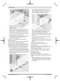
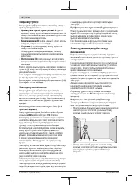
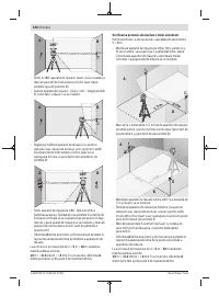
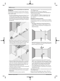
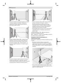
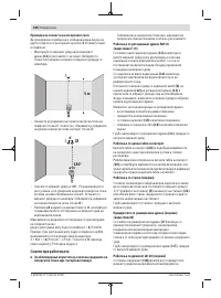
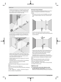
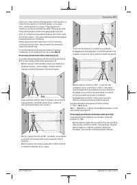
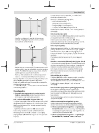
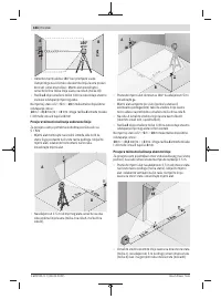
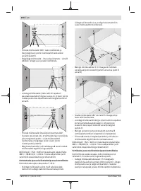
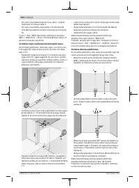
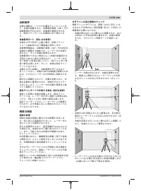
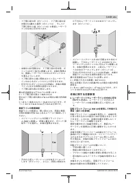
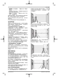
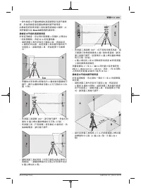
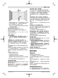
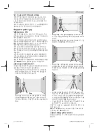
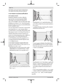
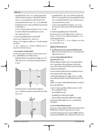
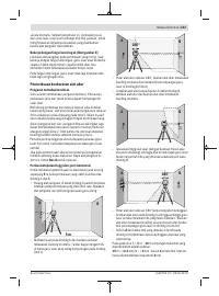
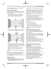
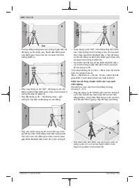
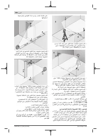
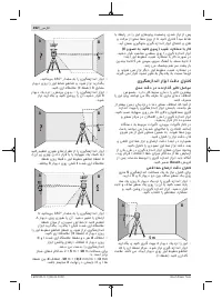
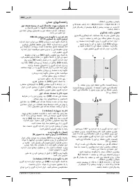
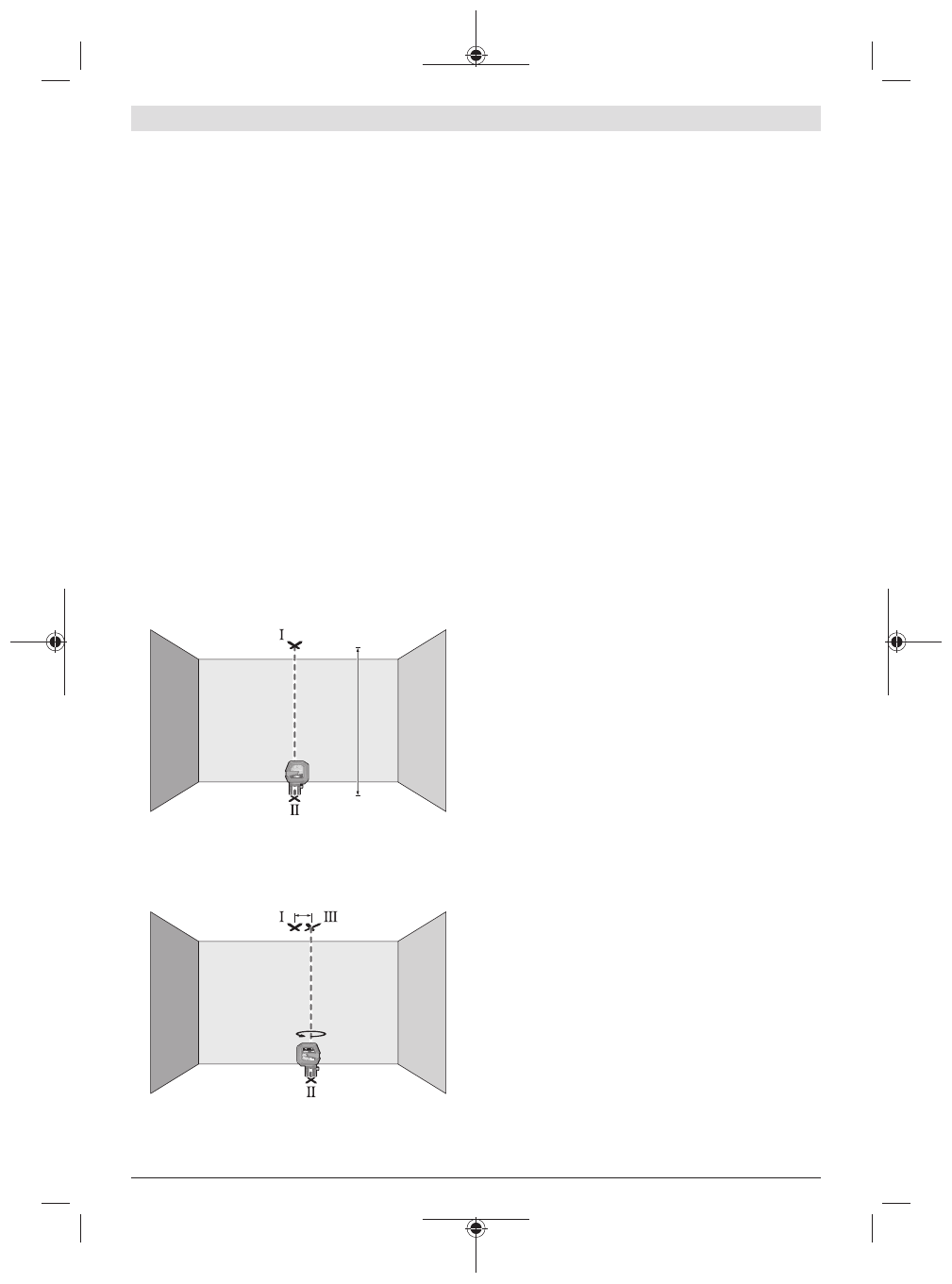
Checking Plumb Accuracy
For this check, you will need a clear measuring space on firm
ground with a distance of approx.
5
m between the floor and
the ceiling.
– Mount the measuring tool onto the rotating mount
(11)
and place it on the floor. Select point mode and allow the
measuring tool to level in.
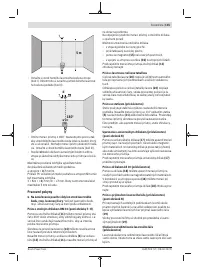
5 m
– Mark the centre of the top laser point on the ceiling
(point I). Also mark the centre of the bottom laser point
on the floor (point II).
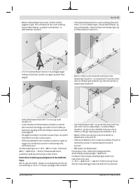
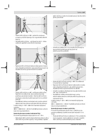
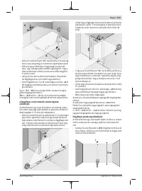
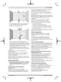
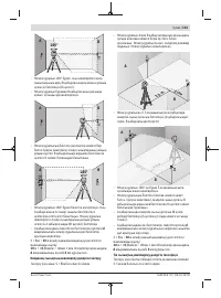
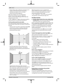
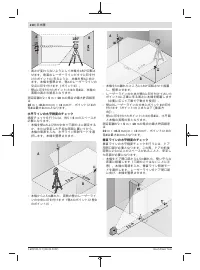
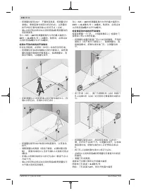
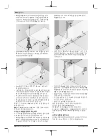
d
180°
– Turn the measuring tool by 180°. Position it so that the
centre of the bottom laser point falls onto the marked
point II. Allow the measuring tool to level in. Mark the
centre of the top laser point (point III).
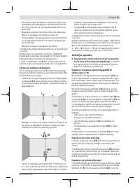
– The discrepancy
d
between the two marked points
Ⅰ
and
Ⅲ
on the ceiling reveals the actual deviation of the meas-
uring tool from the vertical plane.
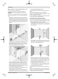
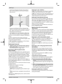
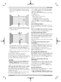
You can calculate the maximum permitted deviation as fol-
lows:
Doubled distance between floor and ceiling ×
0.7
mm/m
Example: At a floor-to-ceiling distance of
5
m, the maximum
deviation amounts to
2 ×
5
m × ±
0.7
mm/m = ±
7
mm. The points
Ⅰ
and
Ⅲ
must
therefore be no further than
7
mm from each other.
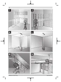
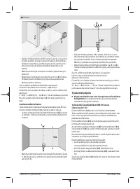
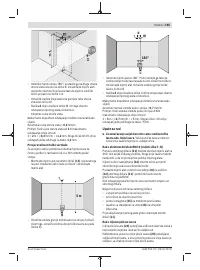
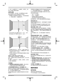
Working Advice
u
Only the centre of the laser point or laser line must be
used for marking.
The size of the laser point/the width of
the laser line changes depending on the distance.
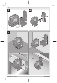
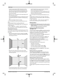
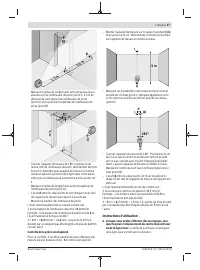
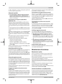
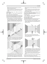
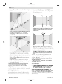
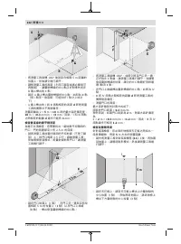
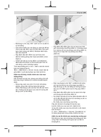
Working with the RM 10 Rotating Mount
(see figures F–H)
You can use the rotating mount
(11)
to rotate the measuring
tool 360° around a central, always visible plumb point. This
enables you to set up the laser lines without having to
change the position of the measuring tool.
You can use the fine adjustment screw
(14)
to align vertical
laser lines precisely with reference points.
Place the measuring tool with the guide groove
(6)
on the
guide rail
(12)
of the rotating mount
(11)
and slide the
measuring tool all the way onto the platform.
To disconnect the measuring tool, pull it off the rotating
mount in the opposite direction.
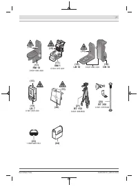
Positioning possibilities of the rotating mount:
– Standing on a flat surface,
– Screwed to a vertical surface,
– On metallic surfaces using the magnets
(15)
,
– On crown moulding using the ceiling clip
(16)
.
Roughly align the rotating mount
(11)
before switching on
the measuring tool.
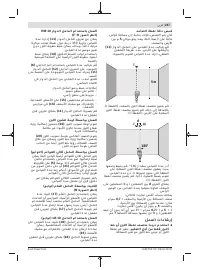
Working with the Laser Target Plate
The laser target plate
(20)
improves visibility of the laser
beam in unfavourable conditions and at greater distances.
The reflective half of the laser target plate
(20)
improves vis-
ibility of the laser line. The transparent half enables the laser
line to be seen from behind the laser target plate.
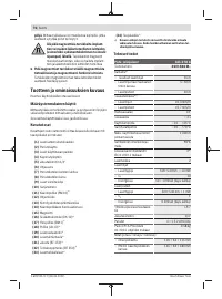
Working with the Tripod (Accessory)
A tripod offers a stable, height-adjustable support surface
for measuring. Place the measuring tool with the 1/4" tripod
mount
(5)
on the thread of the tripod
(21)
or a conventional
camera tripod. Tighten the measuring tool using the locking
screw of the tripod.
Roughly align the tripod before switching on the measuring
tool.
1 609 92A 7LT | (28.04.2022)
Bosch Power Tools
Содержание
- 124 Указания по технике безопасности; Описание продукта и услуг; Применение по назначению
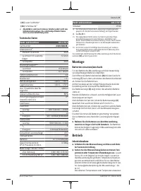
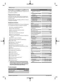
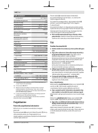
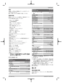
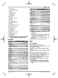
- 125 Технические данные; Сборка; Вставка/замена батареек
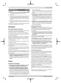
- 126 Работа с инструментом; Включение инструмента
- 130 Указания по применению; Техобслуживание и сервис; Техобслуживание и очистка
- 131 Утилизация; Українська; Вказівки з техніки безпеки
Характеристики

Остались вопросы?Не нашли свой ответ в руководстве или возникли другие проблемы? Задайте свой вопрос в форме ниже с подробным описанием вашей ситуации, чтобы другие люди и специалисты смогли дать на него ответ. Если вы знаете как решить проблему другого человека, пожалуйста, подскажите ему :)


