Электропилы Bosch GCM 10 SD - инструкция пользователя по применению, эксплуатации и установке на русском языке. Мы надеемся, она поможет вам решить возникшие у вас вопросы при эксплуатации техники.
Если остались вопросы, задайте их в комментариях после инструкции.
"Загружаем инструкцию", означает, что нужно подождать пока файл загрузится и можно будет его читать онлайн. Некоторые инструкции очень большие и время их появления зависит от вашей скорости интернета.


English |
33
Bosch Power Tools
1 609 92A 0XL | (29.9.14)
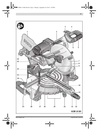
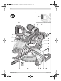
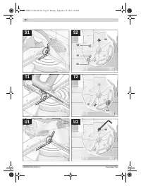
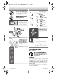
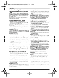
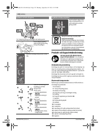
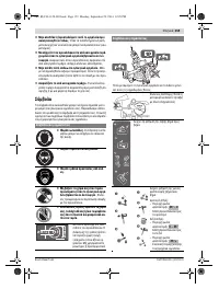
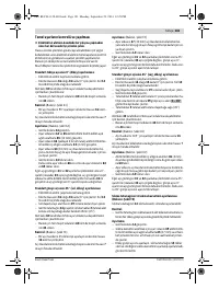
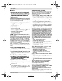
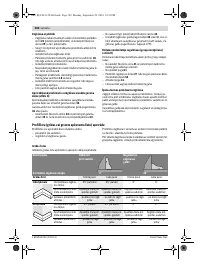
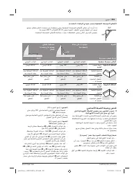
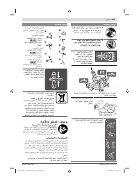
Bevel angle range
– Pull the left fence extension
19
completely outward. (see
“Extending the Fence”, page 32)
– Loosen the lock lever
14
.
– Tilt the tool arm leftward via handle
5
until the angle indica-
tor
31
indicates the desired bevel angle.
– Hold the tool arm in this position and retighten the clamp-
ing lever
14
.
The clamping force of the clamping lever must securely
hold the position of the tool arm at any bevel angle.
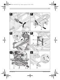
Bevel angle range
(see figure K)
– Pull the right fence extension
19
completely outward.(see
“Extending the Fence”, page 32)
– Loosen the lock lever
14
.
– Lightly tilt the tool arm leftward out of the 0 ° position via
handle
5
and turn knob
39
until the desired bevel angle
range is indicated.
– Tilt the tool arm via handle
5
to the right until angle indica-
tor
22
indicates the desired bevel angle.
– Hold the tool arm in this position and retighten the clamp-
ing lever
14
.
The clamping force of the clamping lever must securely
hold the position of the tool arm at any bevel angle.
Standard 0 ° Bevel Angle
To enable simple and swift resetting of the standard 0 ° bevel
angle, knob
39
will engage in the
bevel angle range.
– Tilt the tool arm from right to left over the 0 ° position.
Bevel angle range
– Pull both fence extensions
19
completely outward.(see
“Extending the Fence”, page 32)
– Loosen the lock lever
14
.
– Lightly tilt the tool arm leftward out of the 0 ° position via
handle
5
and turn knob
39
until the desired bevel angle
range is indicated.
– Tilt the tool arm via handle
5
to the left or right until angle
indicator
31
or
22
indicate the desired bevel angle.
– Hold the tool arm in this position and retighten the clamp-
ing lever
14
.
The clamping force of the clamping lever must securely
hold the position of the tool arm at any bevel angle.
Standard 33.9 ° Bevel Angle
–
Standard angle 33.9 °:
Pull adjustment knob
32
completely outward and turn it by
90 °. Now tilt the tool arm via the handle
5
until the tool arm
can be heard to engage.
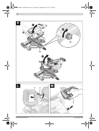
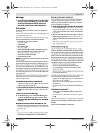
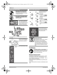
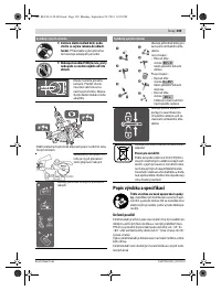
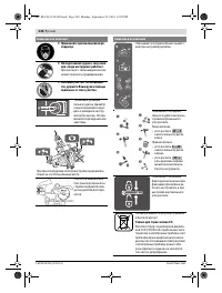
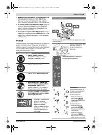
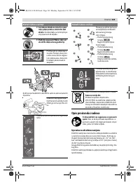
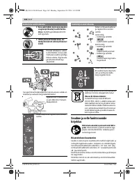
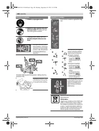
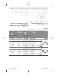
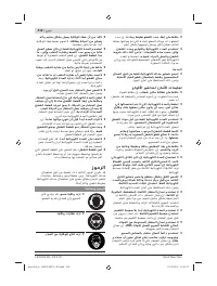
Adjusting the Handle (see figure L)
For a more convenient hand position, the handle
5
can be
turned to 4 different positions.
– Loosen clamp
3
.
– Grasp and pull tongue
4
outward, then turn handle
5
until
it engages in the desired position.
– Let go of tongue
4
again and lock clamp
3
.
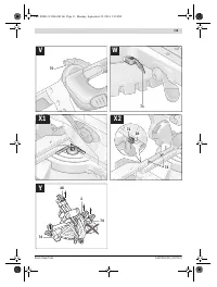
Starting Operation
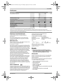
Observe correct mains voltage! The voltage of the pow-
er source must agree with the voltage specified on the
nameplate of the machine. Power tools marked with
230 V can also be operated with 220 V.
Switching On (see figure M)
– To
start
the machine, press the On/Off switch
25
and keep
it pressed.
Note:
For safety reasons, the On/Off switch
25
cannot be
locked; it must remain pressed during the entire operation.
The locking lever
41
will only disengage the retracting blade
guard
8
after pressing button
6
, so that the tool arm can be
lowered.
– For
sawing
, you must press button
6
in addition to actuat-
ing the On/Off switch.
To save energy, only switch the power tool on when using it.
Switching Off
– To
switch off
the machine, release the On/Off switch
25
.
Working Advice
General Sawing Instructions
For all cuts, it must first be ensured that the saw blade
at no time can come in contact with the fence, screw
clamps or other machine parts. Remove any mounted
auxiliary stops or adjust them accordingly.
Protect the saw blade against impact and shock. Do not sub-
ject the saw blade to lateral pressure.
Do not saw warped/bent workpieces. The workpiece must
always have a straight edge to face against the fence.
Long workpieces must be underlaid or supported at their free
end.
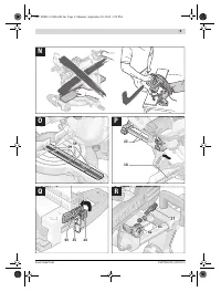
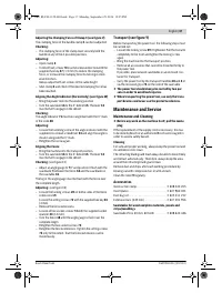
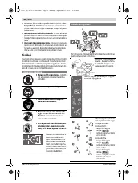
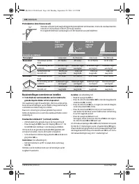
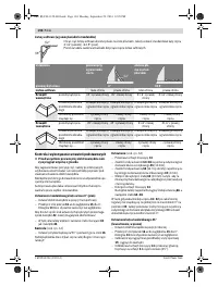
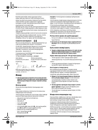
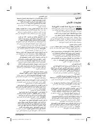
Position of the Operator (see figure N)
Do not stand in a line with the saw blade in front of the
machine. Always stand aside of the saw blade.
This pro-
tects your body against possible kickback.
– Keep hands, fingers and arms away from the rotating saw
blade.
– Do not cross your arms when operating the tool arm.
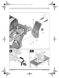
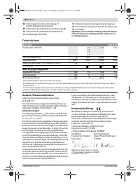
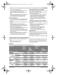
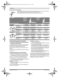
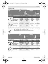
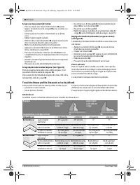
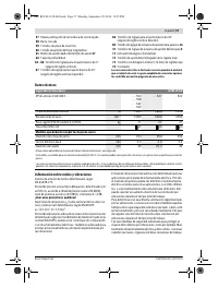
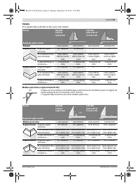
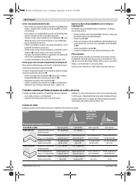
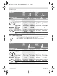
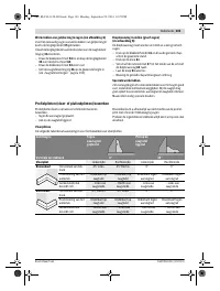
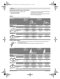
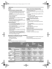
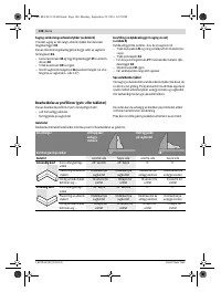
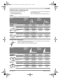
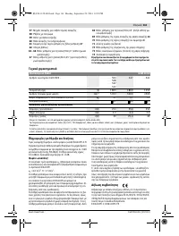
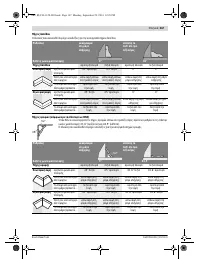
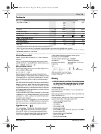
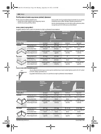
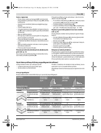
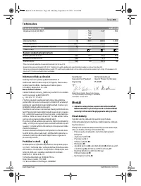
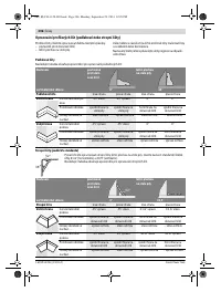
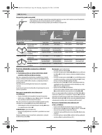
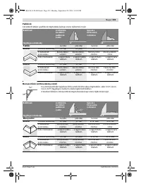
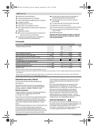
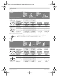
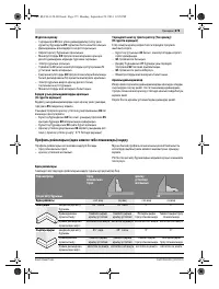
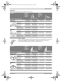
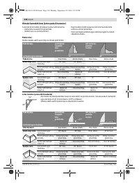
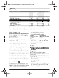
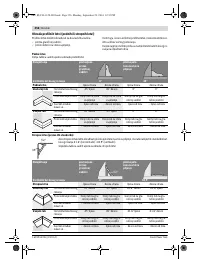
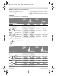
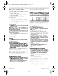
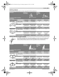
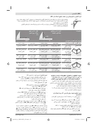
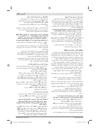
Permissible Workpiece Dimensions
Maximum
workpiece sizes:
Minimum
workpiece sizes (= all workpieces that can be
clamped left or right from the saw blade with the provided
quick-action clamp
21
): 145 x 40 mm (length x width)
Cutting depth, max.
(0 °/0 °): 85 mm
45°– 0
0 – 45°
45°– 0
45°+
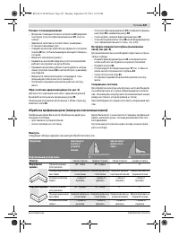
Mitre/Bevel Angle
Height x Width [mm]
Horizontal
Vertical
0 °
0 °
85 x 305
45 °
0 °
85 x 216
0 °
45 ° (leftward)
50 x 305
0 °
45 ° (rightward)
32 x 305
45 °
45 ° (leftward)
50 x 216
45 °
45 ° (rightward)
32 x 216
OBJ_BUCH-1128-003.book Page 33 Monday, September 29, 2014 12:25 PM
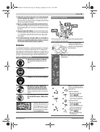
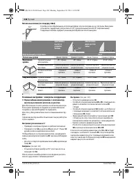
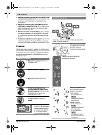
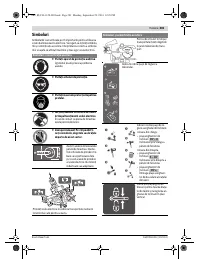
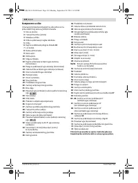
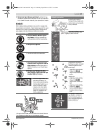
Содержание
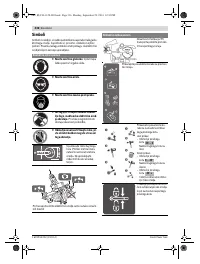
- 238 Защищайте электроинструмент от дождя и сырости.
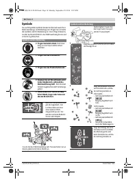
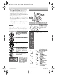
- 239 Держите Ваше рабочее место в чистоте.; Символы; Символы и их значение
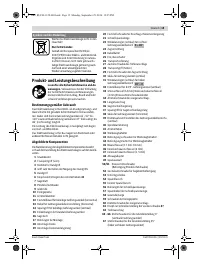
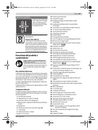
- 241 Описание продукта и услуг; Применение по назначению
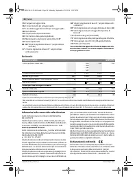
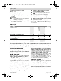
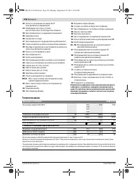
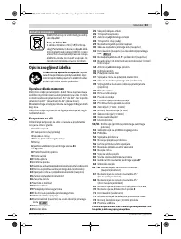
- 242 Технические данные; Применяйте средства защиты органов слуха!; Заявление о соответствии; Сборка; Комплект поставки; Панельная пила; Размеры пильных дисков
- 243 Стационарный или временный монтаж; Монтаж на верстаке производства Bosch; Отсос пыли и стружки; Внешняя система пылеотсоса
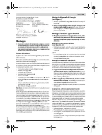
- 244 Демонтаж пильного диска; Работа с инструментом; Подготовка к эксплуатации
- 245 Настройка вертикального угла распила; угол распила
- 246 Включение электроинструмента; Угол распила
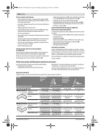
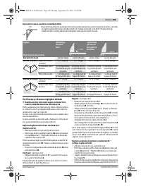
- 247 Резание с тяговым движением; Обработка профильных реек (плинтусов и потолочных планок); Плинтусы
- 248 Основные настройки – контроль и коррекция; Настройка угла наклона в 0 °
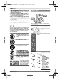
- 250 Настройка упорной планки; Техобслуживание и сервис; Техобслуживание и очистка; Очистка; Принадлежности
- 251 Россия; Утилизация


