Электропилы Bosch GCM 10 SD - инструкция пользователя по применению, эксплуатации и установке на русском языке. Мы надеемся, она поможет вам решить возникшие у вас вопросы при эксплуатации техники.
Если остались вопросы, задайте их в комментариях после инструкции.
"Загружаем инструкцию", означает, что нужно подождать пока файл загрузится и можно будет его читать онлайн. Некоторые инструкции очень большие и время их появления зависит от вашей скорости интернета.


32
| English
1 609 92A 0XL | (29.9.14)
Bosch Power Tools
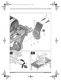
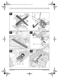
– Mount the clamping flange
54
, the washer
53
and the hex-
agon bolt
52
.
Press spindle lock
40
until it engages and tighten hexagon
bolt
52
with the supplied socket spanner
33
in anticlock-
wise direction with a tightening torque of approx.
15 – 23 Nm.
– Push the locking lever
41
and guide the retracting blade
guard
8
down again.
– Retighten the screws
49
and
50
.
Operation
Before any work on the machine itself, pull the mains
plug.
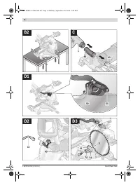
Transport Safety (see figure E)
The transport safety-lock
26
enables easier handling of the
machine when transporting to various working locations.
Releasing the Machine (Working Position)
– Push the tool arm by the handle
5
down a little in order to
relieve the transport safety-lock
26
.
– Pull the transport safety-lock
26
all the way outward and
turn it by 90 °. Allow the transport safety-lock to engage in
this position.
– Guide the tool arm slowly upward.
Securing the Machine (Transport Position)
– Loosen the locking screw
29
if tightened. Pull the tool arm
completely to the front and tighten the locking screw
again.
– Screw the depth stop
62
completely to the top. (see “Ad-
justing the Depth Stop”, page 34)
– To lock the saw table
16
, tighten the locking knob
12
.
– Pull the transport safety-lock
26
all the way outward and
turn it by 90 °. Allow the transport safety-lock to engage in
this position.
– Push the locking lever
41
and at the same time lower the
tool arm via handle
5
until the transport safety-lock engag-
es in the end position.
The tool arm is now securely locked for transport.
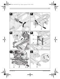
Preparing for Operation
Extending the Saw Table (see figure F)
Long workpieces must be underlaid or supported at their free
end.
– Push tensioning lever
37
upward.
– Pull out saw-table extension
36
to the desired length (max.
225 mm).
– Lock in place by pushing tensioning lever
37
down again.
Extending the Fence (see figure G)
For bevel angles, the fence extensions
19
must be moved.
– Loosen the locking screw
20
and pull the fence extension
19
completely outward.
– Retighten the screw again.
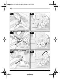
Clamping the Workpiece (see figure H)
To ensure optimum working safety, the workpiece must al-
ways be firmly clamped.
Do not saw workpieces that are too small to clamp.
While clamping the workpiece, do not reach under the
clamping lever of the quick-action clamp with your fin-
gers.
– Press the workpiece firmly against the fence
18
.
– Insert the quick-action clamp
21
into one of the holes
56
intended for this purpose.
– Adapt the quick-action clamp to the workpiece by turning
the threaded rod
58
.
– Push on the clamping lever
57
in order to clamp the work-
piece.
Adjusting Mitre Angles
To ensure precise cuts, the basic adjustment of the machine
must be checked and adjusted as necessary after intensive
use (see “Checking and Adjusting the Basic Adjustment”,
page 36).
Always tighten the locking knob 12 firmly before saw-
ing.
Otherwise the saw blade can become wedged in the
workpiece.
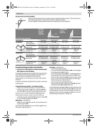
Adjusting Standard Mitre Angles (see figure I)
For quick and precise adjustment of commonly used mitre an-
gles, detents
15
have been provided for on the saw table:
– Loosen the locking knob
12
in case it is tightened.
– Pull lever
13
and rotate the saw table
16
left or right to the
requested detent.
– Release the lever again. The lever must be felt to engage in
the detent.
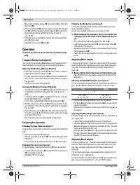
Adjusting Any Mitre Angle (see figure J)
The mitre angle can be set in the range from 52 ° (left side) to
60 ° (right side).
– Loosen the locking knob
12
in case it is tightened.
– Pull lever
13
and at the same time push the locking bracket
11
until it engages in the groove intended for this. The saw
table can be moved freely now.
– Turn the saw table
16
left or right by the locking knob until
the angle indicator
71
indicates the requested mitre angle.
– Tighten the locking knob
12
again.
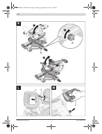
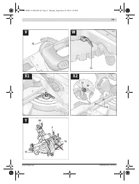
Adjusting Bevel Angles
To ensure precise cuts, the basic adjustment of the machine
must be checked and adjusted as necessary after intensive
use (see “Checking and Adjusting the Basic Adjustment”,
page 36).
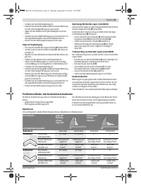
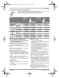
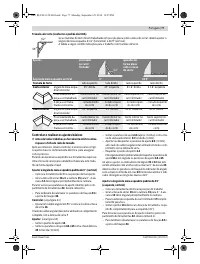
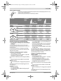
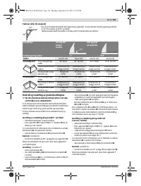
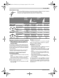
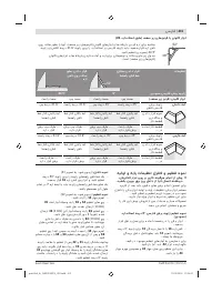
The vertical bevel angle can be adjusted in a range from 47 °
(leftward) to 46 ° (rightward).
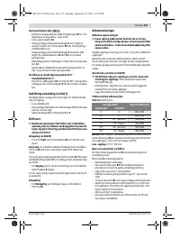
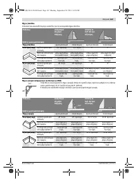
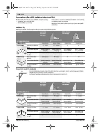
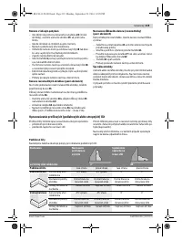
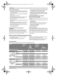
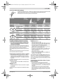
For quick and precise adjustment of commonly used bevel an-
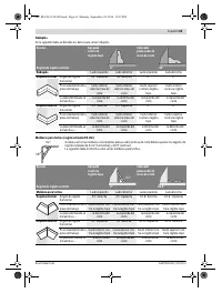
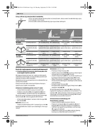
gles, stops are provided for 0 °, 45 ° and 33.9 ° angles.
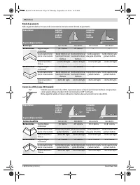
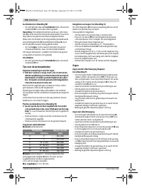
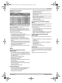
Left
Right
0 °
15 °; 22.5 °;
31.6 °; 45 °; 52 °
15 °; 22.5 °;
31.6 °; 45 °; 60 °
OBJ_BUCH-1128-003.book Page 32 Monday, September 29, 2014 1:31 PM
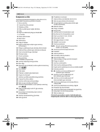
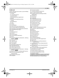
Содержание
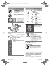
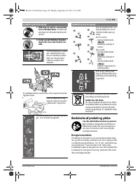
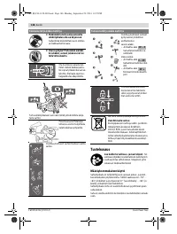
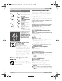
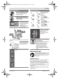
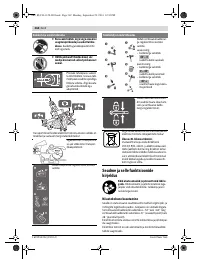
- 238 Защищайте электроинструмент от дождя и сырости.
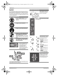
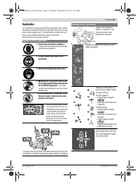
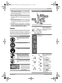
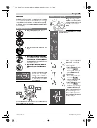
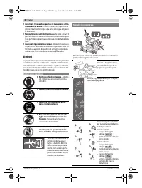
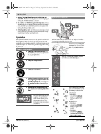
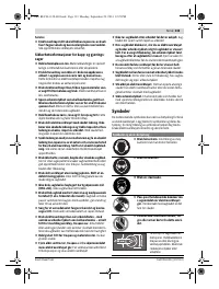
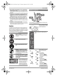
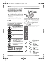
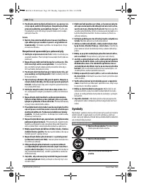
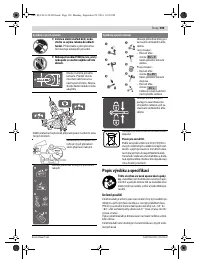
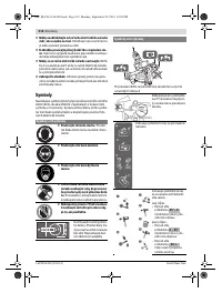
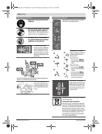
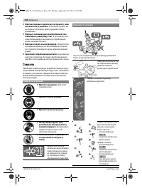
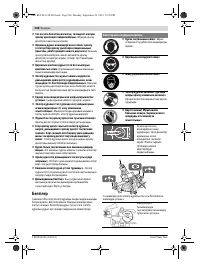
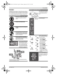
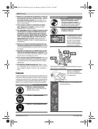
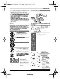
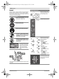
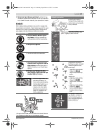
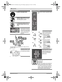
- 239 Держите Ваше рабочее место в чистоте.; Символы; Символы и их значение
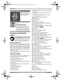
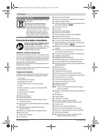
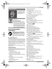
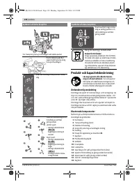
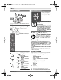
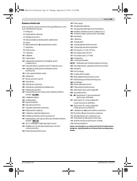
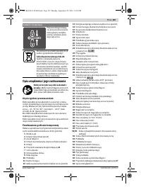
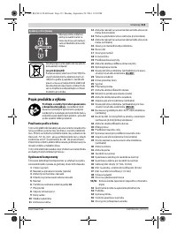
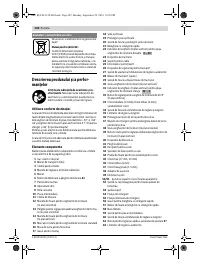
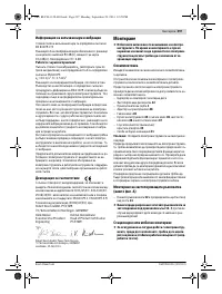
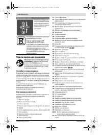
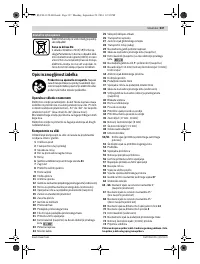
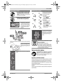
- 241 Описание продукта и услуг; Применение по назначению
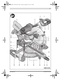
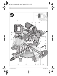
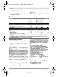
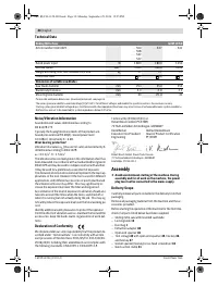
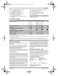
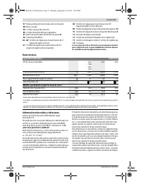
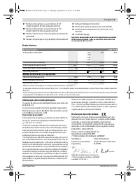
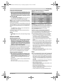
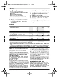
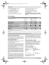
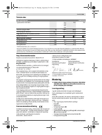
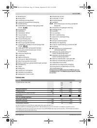
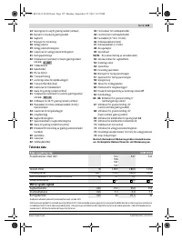
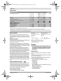
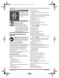
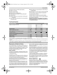
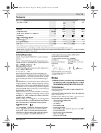
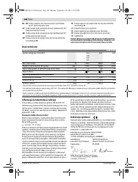
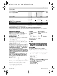
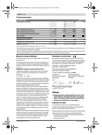
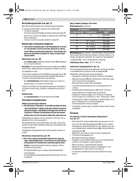
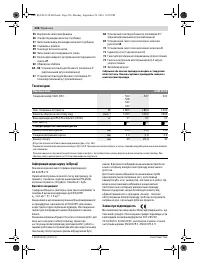
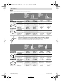
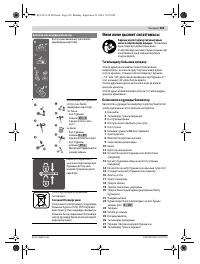
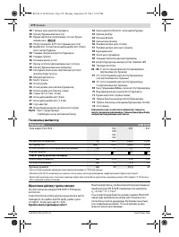
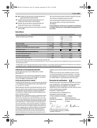
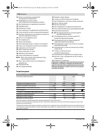
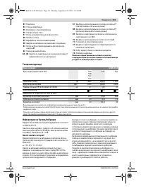
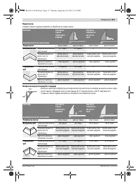
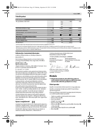
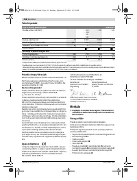
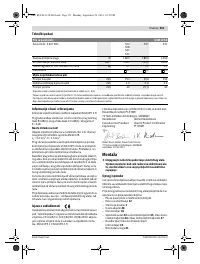
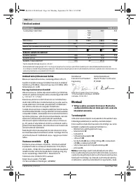
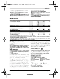
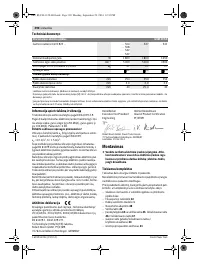
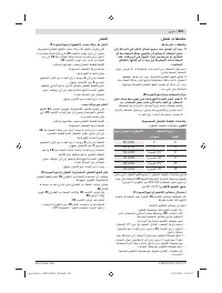
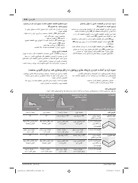
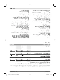
- 242 Технические данные; Применяйте средства защиты органов слуха!; Заявление о соответствии; Сборка; Комплект поставки; Панельная пила; Размеры пильных дисков
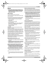
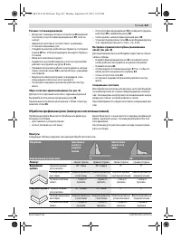
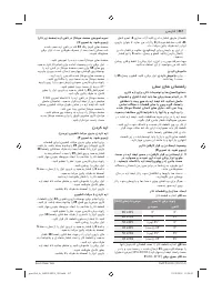
- 243 Стационарный или временный монтаж; Монтаж на верстаке производства Bosch; Отсос пыли и стружки; Внешняя система пылеотсоса
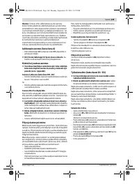
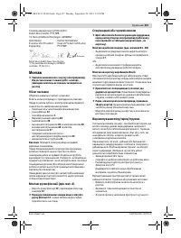
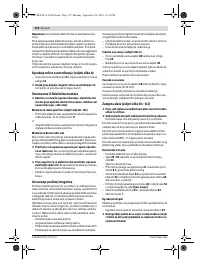
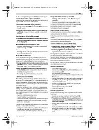
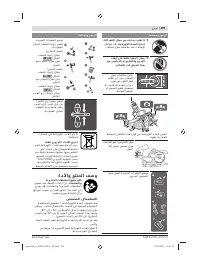
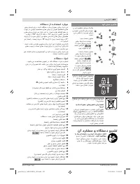
- 244 Демонтаж пильного диска; Работа с инструментом; Подготовка к эксплуатации
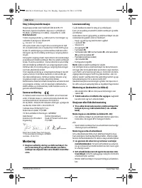
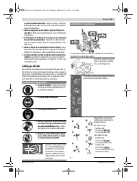
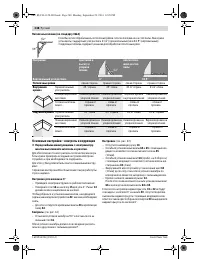
- 245 Настройка вертикального угла распила; угол распила
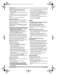
- 246 Включение электроинструмента; Угол распила
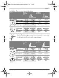
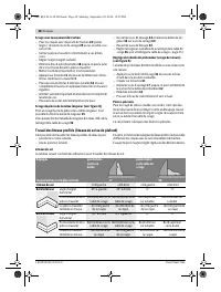
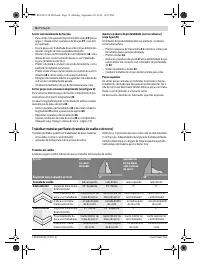
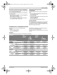
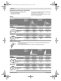
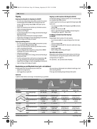
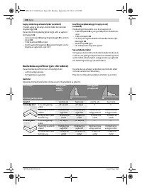
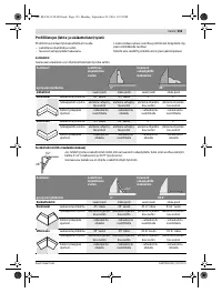
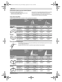
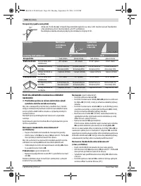
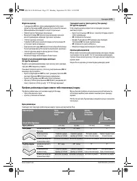
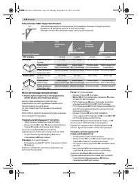
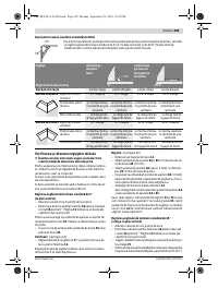
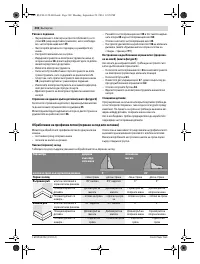
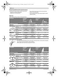
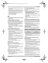
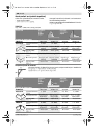
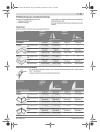
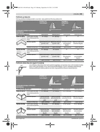
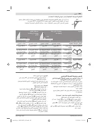
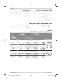
- 247 Резание с тяговым движением; Обработка профильных реек (плинтусов и потолочных планок); Плинтусы
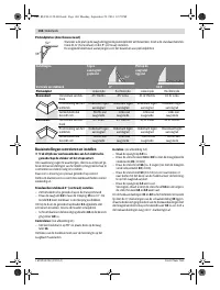
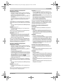
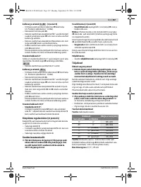
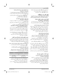
- 248 Основные настройки – контроль и коррекция; Настройка угла наклона в 0 °
- 250 Настройка упорной планки; Техобслуживание и сервис; Техобслуживание и очистка; Очистка; Принадлежности
- 251 Россия; Утилизация


