Кондиционеры Daikin AHQ-C - инструкция пользователя по применению, эксплуатации и установке на русском языке. Мы надеемся, она поможет вам решить возникшие у вас вопросы при эксплуатации техники.
Если остались вопросы, задайте их в комментариях после инструкции.
"Загружаем инструкцию", означает, что нужно подождать пока файл загрузится и можно будет его читать онлайн. Некоторые инструкции очень большие и время их появления зависит от вашей скорости интернета.


1-9
English
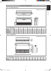
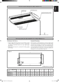
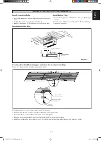
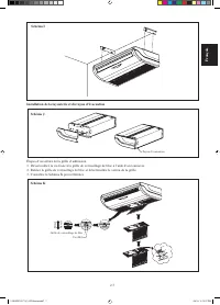
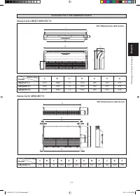
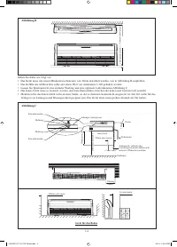
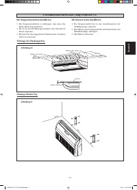
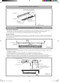
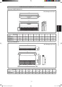
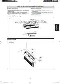
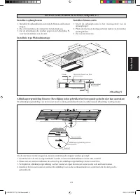
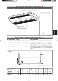
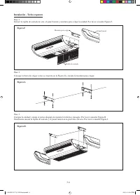
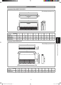
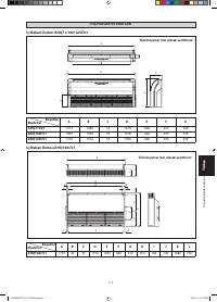
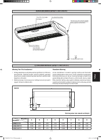
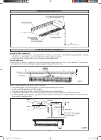
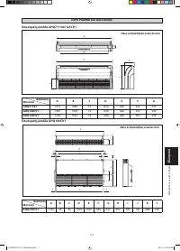
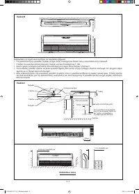
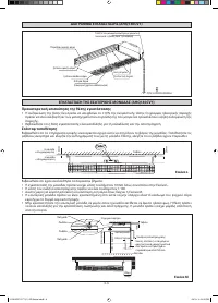
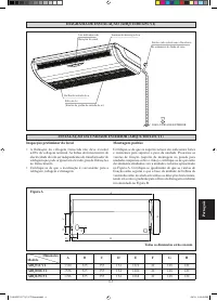
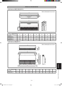
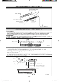
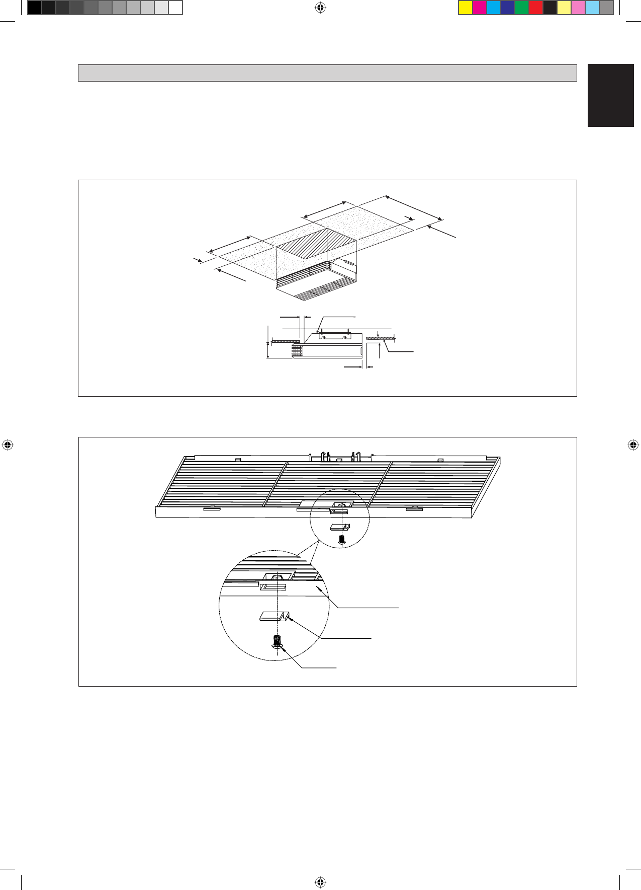
UNDER CEILING INSTALLATION (AHQ140CV1)
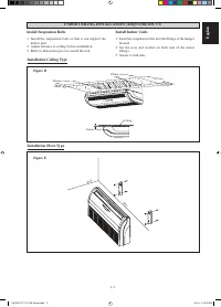
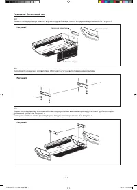
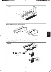
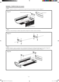
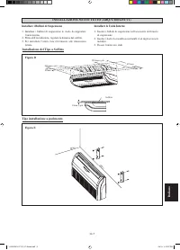
Install Suspension Bolts
Install the suspension bolts so that it can support the indoor
unit.
Adjust distance to ceiling before installation.
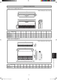
Refer to dimension given by Figure N to install the unit.
1.
2.
3.
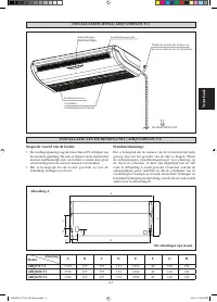
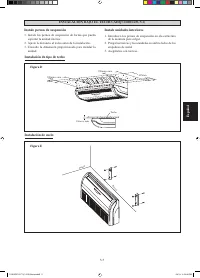
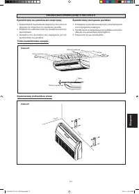
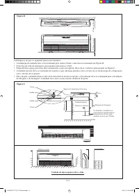
Install Indoor Units
Insert the suspension bolts into the
fi
tting of the hanger.
bracket.
Set the nuts and washer on both side of the metal
fi
ttings.
Secure it with nuts.
1.
2.
3.
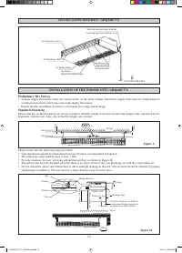
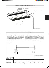
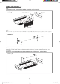
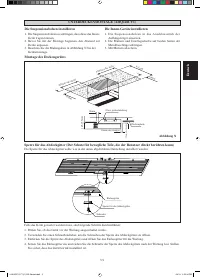
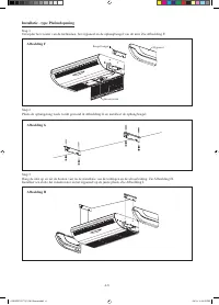
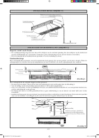
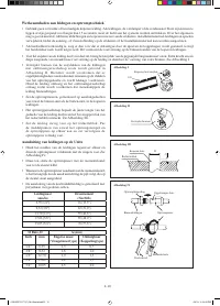
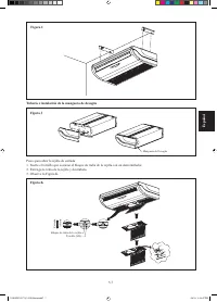
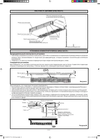
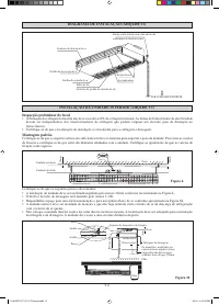
Installation Ceiling Type
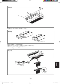
Figure N
10mm or less
Top Panel Of Unit
Ceiling Board
10mm
145-155mm
10mm
300mm or more
10mm
621mm
10mm or less
300mm or more
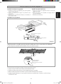
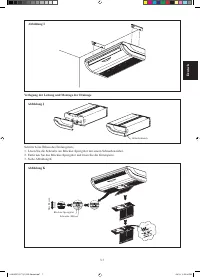
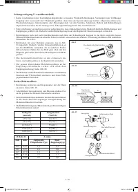
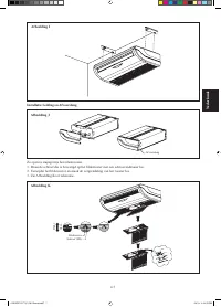
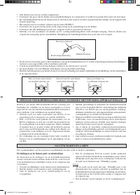
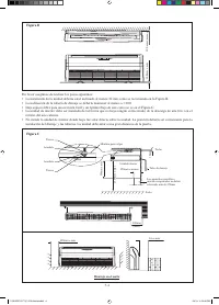
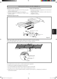
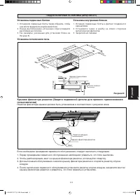
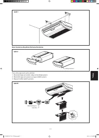
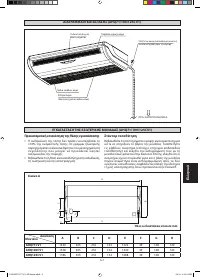
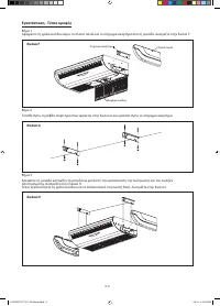
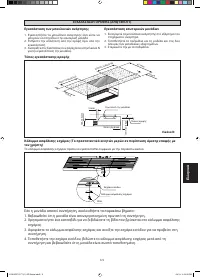
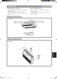
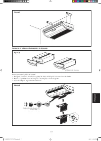
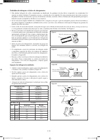
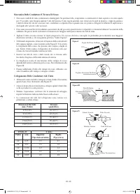
Cover Lock Grille (The moving part protection for user direct touching)
Cover lock grille must be installed as the figure below.
Intake Grille
Cover Lock Grille
Screw
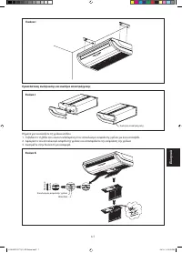
If the unit need to be service, steps below shall be followed:
Confirm that the unit had been switched off before servicing the unit.
Use screwdriver to unlock the screw on the cover lock grille.
Remove the cover lock grille and open the intake grille for the service purpose.
Install the intake grille and screw the cover lock grille after service and make sure the unit is proper install.
1.
2.
3.
4.
1 IM 5CEY-0711(1)-EN-Siesta.indd9 9
1 IM 5CEY-0711(1)-EN-Siesta.indd9 9
4/3/13 3:25:53 PM
4/3/13 3:25:53 PM
Содержание
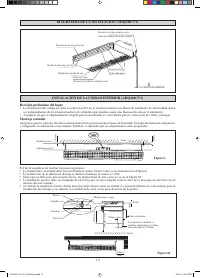
- 64 МЕРЫ ПРЕДОСТОРОЖНОСТИ; ВHИMAHИE; РУКОВОДСТВО ПО УСТАНОВКЕ; ПPEДУПPEЖДEHИE
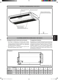
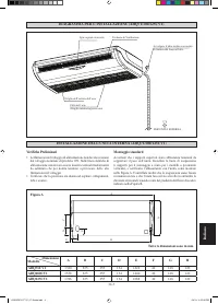
- 65 Предварительный осмотр места установки; Рисунок A
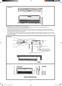
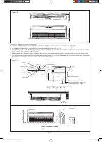
- 66 Рисунок B; Удостоверьтесь, что следующие операции предприняты:; Рисунок C; Напольный вертикальный вид
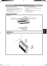
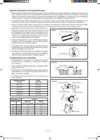
- 67 Установка подвесных болтов; Рисунок D; Установка внутренних блоков
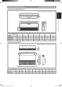
- 68 Установка - Потолочный тип; Рисунок F
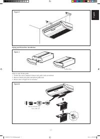
- 69 Рисунок I; Открытие решетки впуска воздуха; Рисунок K; Pисунок J
- 70 Рисунок L; Рисунок M
- 71 Рисунок N
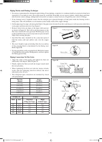
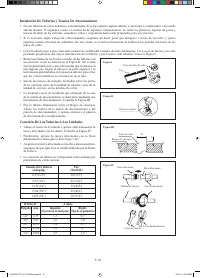
- 72 Соединение Трубопроводов К блокам
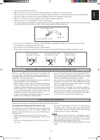
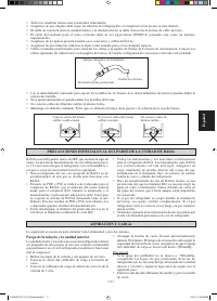
- 73 Прикрепите изоляционный рукав; Вакуумирование трубопровода и внутреннего блока; Осторожно


