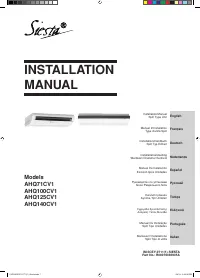
Кондиционеры Daikin AHQ-C - инструкция пользователя по применению, эксплуатации и установке на русском языке. Мы надеемся, она поможет вам решить возникшие у вас вопросы при эксплуатации техники.
Если остались вопросы, задайте их в комментариях после инструкции.
"Загружаем инструкцию", означает, что нужно подождать пока файл загрузится и можно будет его читать онлайн. Некоторые инструкции очень большие и время их появления зависит от вашей скорости интернета.


1-8
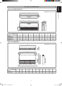
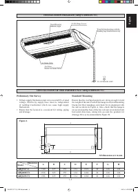
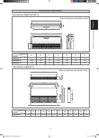
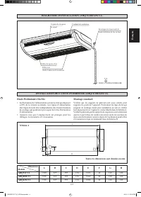
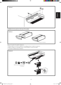
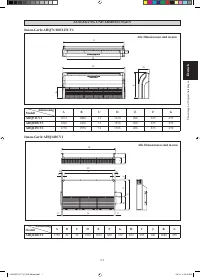
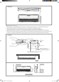
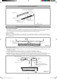
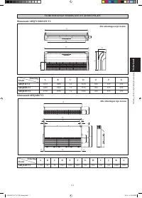
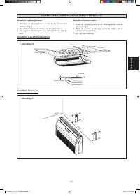
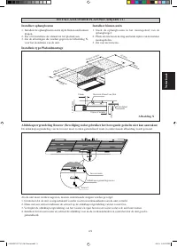
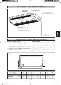
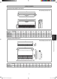
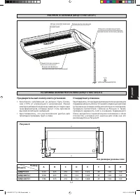
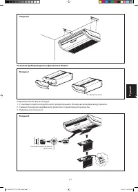
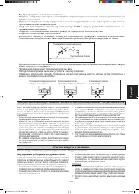
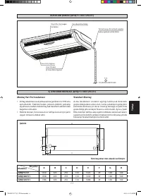
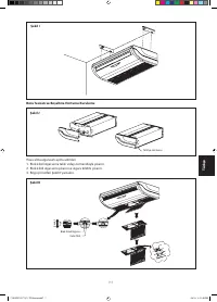
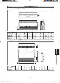
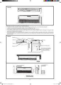
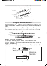
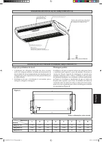
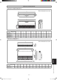
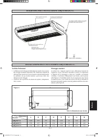
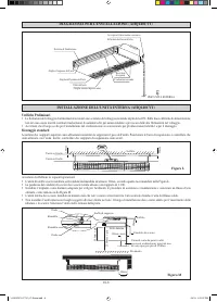
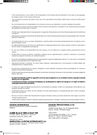
INSTALLATION DIAGRAM (AHQ140CV1)
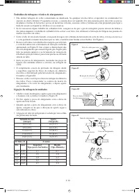
Air Discharge Louver
Indicator Light
Air Discharge Grille
Air Intake Grille
Signal Receiver
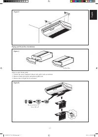
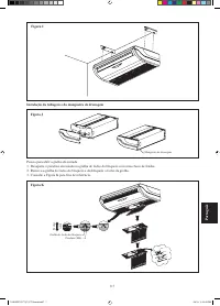
Wrap the Insulated pipe with the
finishing tape from bottom to top
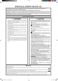
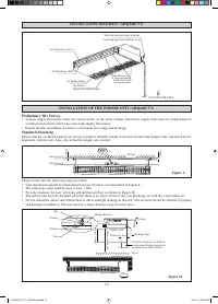
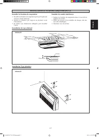
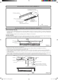
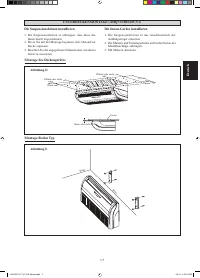
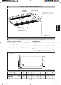
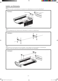
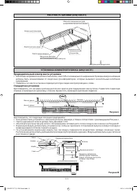
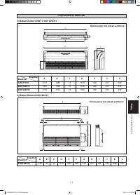
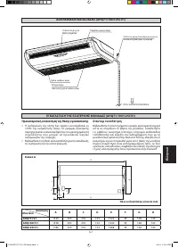
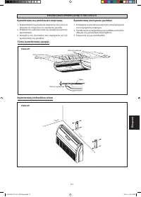
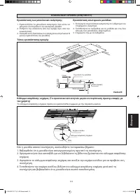
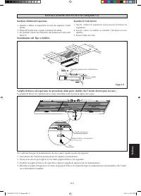
INSTALLATION OF THE INDOOR UNIT (AHQ140CV1)
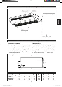
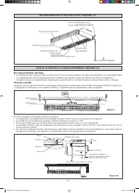
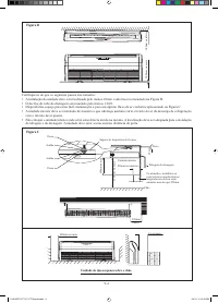
Preliminary Site Survey
Voltage supply fluctuation must not exceed ±10% of the rated voltage. Electricity supply lines must be independent of
welding transformers which can cause high supply fluctuation.
Ensure that the installation location is convenient for wiring and drainage.
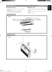
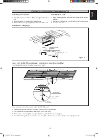
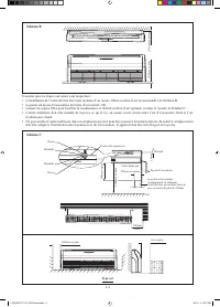
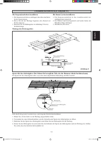
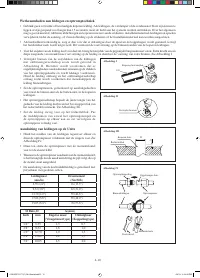
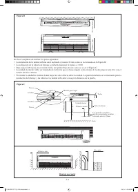
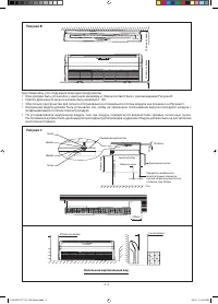
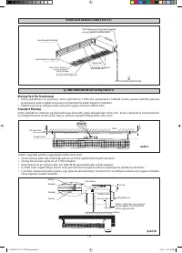
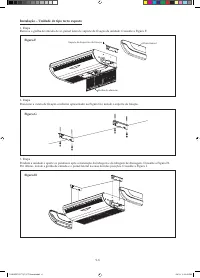
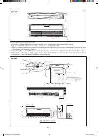
Standard Mounting
Ensure that the overhead supports are strong enough to hold the weight of the unit. Position the hanger rods, and check for its
alignment with the unit. Also, check that the hangers are secured.
•
•
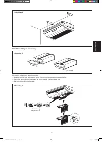
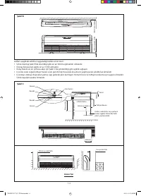
Figure L
10mm
20mm
Ceiling
Unit at level
Unit at level
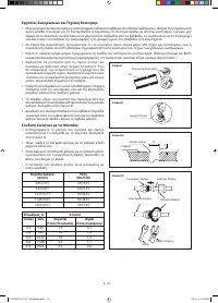
TO OUTDOOR UNIT
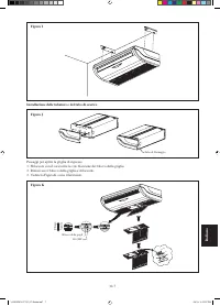
Air Filters
(Inside Air Intake Grille)
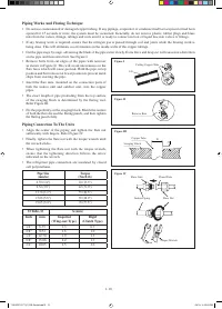
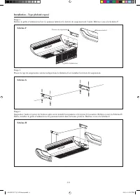
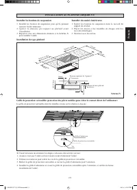
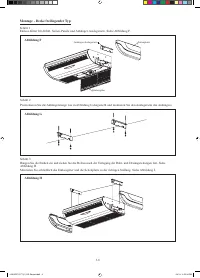
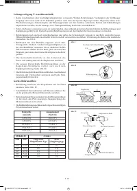
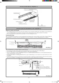
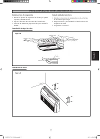
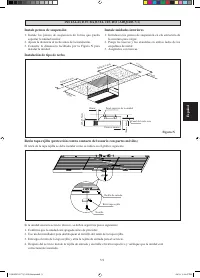
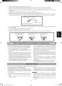
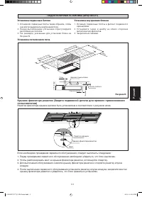
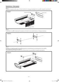
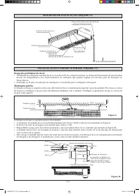
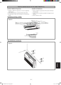
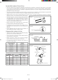
Please ensure that the following steps are taken:
Unit installation should be tilted/slanted at least 10mm as recommended in Figure L.
The drain pipe slope shall be kept at least 1:100.
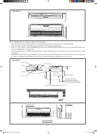
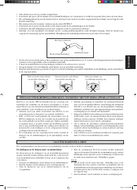
Provide clearance for easy servicing and optimal air flow as shown in Figure M.
The indoor unit must be installed such that there is no short circuit of the cool discharge air with the warm return air.
Do not install the indoor unit where there is direct sunlight shining on the unit. The location should be suitable for piping
and drainage installation. The unit must be a large distance away from the door.
•
•
•
•
•
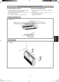
Figure M
Utensils, furnitures or built-in
architectural features must not
protrude more than 250mm
Drainage Pipe
250mm or less
300mm
(Min.)
500mm or more
10mm
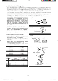
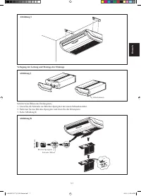
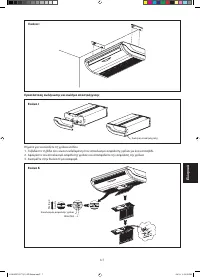
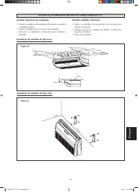
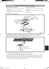
Indoor Unit
Hanger Bracket
Nut
Washer
Washer
Nut
Floor
2300mm or more
Ceiling
1 IM 5CEY-0711(1)-EN-Siesta.indd8 8
1 IM 5CEY-0711(1)-EN-Siesta.indd8 8
4/3/13 3:25:53 PM
4/3/13 3:25:53 PM
Содержание
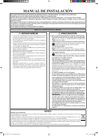
- 64 МЕРЫ ПРЕДОСТОРОЖНОСТИ; ВHИMAHИE; РУКОВОДСТВО ПО УСТАНОВКЕ; ПPEДУПPEЖДEHИE
- 65 Предварительный осмотр места установки; Рисунок A
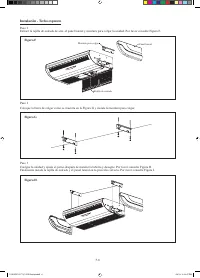
- 66 Рисунок B; Удостоверьтесь, что следующие операции предприняты:; Рисунок C; Напольный вертикальный вид
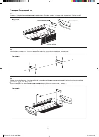
- 67 Установка подвесных болтов; Рисунок D; Установка внутренних блоков
- 68 Установка - Потолочный тип; Рисунок F
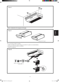
- 69 Рисунок I; Открытие решетки впуска воздуха; Рисунок K; Pисунок J
- 70 Рисунок L; Рисунок M
- 71 Рисунок N
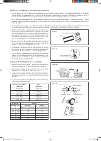
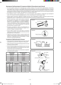
- 72 Соединение Трубопроводов К блокам
- 73 Прикрепите изоляционный рукав; Вакуумирование трубопровода и внутреннего блока; Осторожно


