Кондиционеры Daikin FWP-AT - инструкция пользователя по применению, эксплуатации и установке на русском языке. Мы надеемся, она поможет вам решить возникшие у вас вопросы при эксплуатации техники.
Если остались вопросы, задайте их в комментариях после инструкции.
"Загружаем инструкцию", означает, что нужно подождать пока файл загрузится и можно будет его читать онлайн. Некоторые инструкции очень большие и время их появления зависит от вашей скорости интернета.


FC66003946
Rev 00
USER MANUAL
It is strictly forbidden to reproduce this manual, even par tially
EN
22
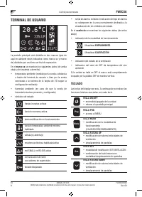
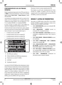
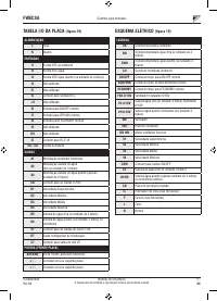
FWECSA
Controller for units
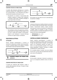
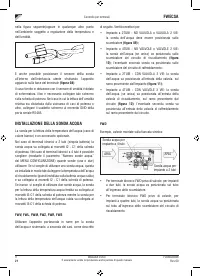
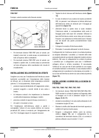
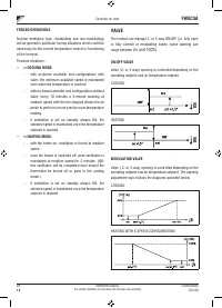
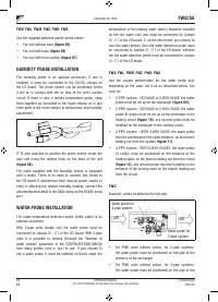
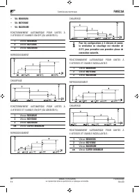
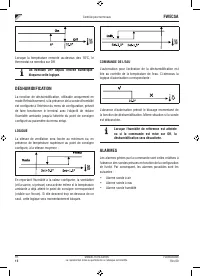
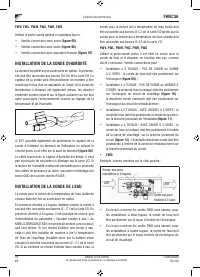
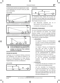
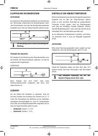
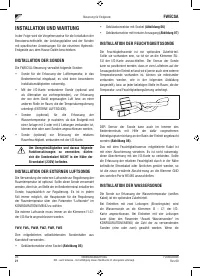
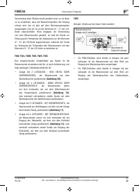
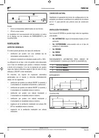
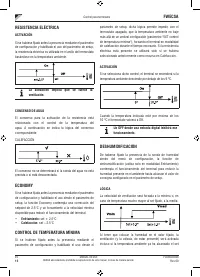
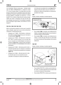
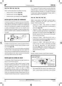
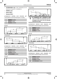
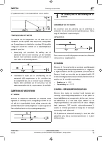
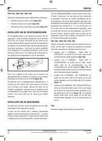
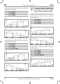
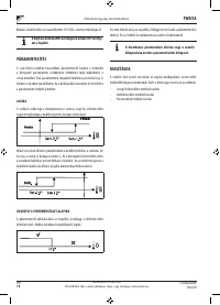
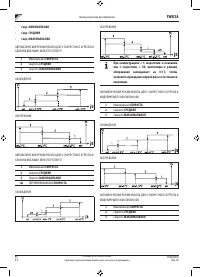
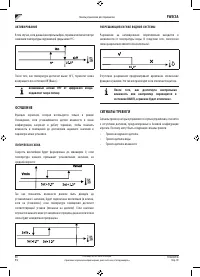
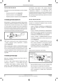
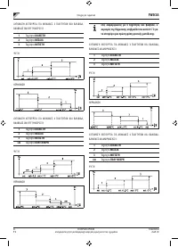
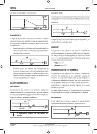
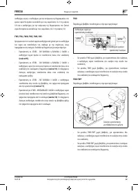
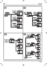
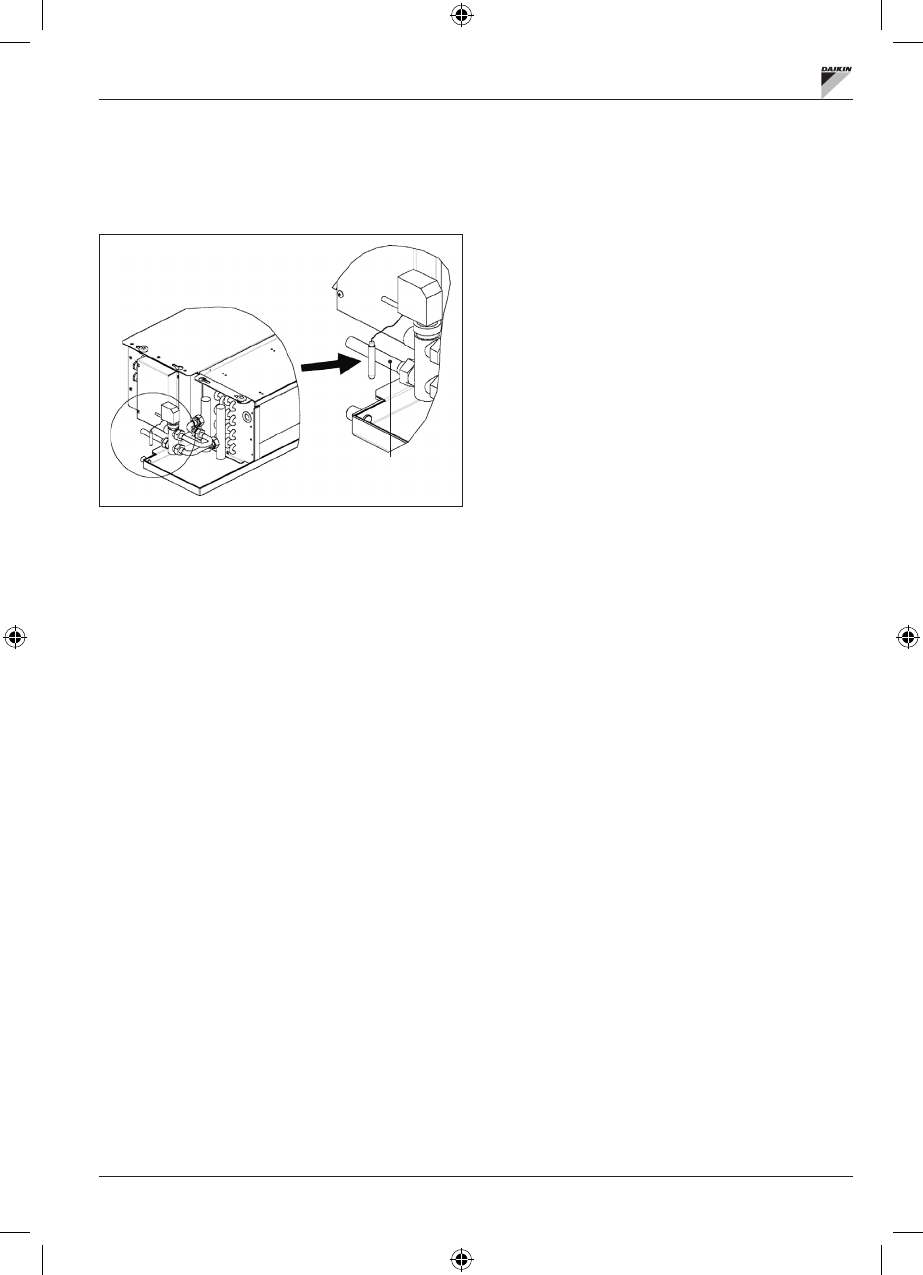
entrance of the exchanger in the heating circuit.
FWB-FWP
Example, valves installed on the left side:
System pipe
supplied by the customer
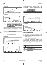
•
For FWB-FWP units without valves, for 2-pipe systems,
the water probe must be positioned on the pipe at the
entrance of the exchanger.
•
For FWB-FWP units without valves, for 4-pipe systems,
the water probe must be positioned on the pipe at the
entrance of the exchanger in the heating circuit.
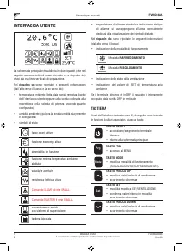
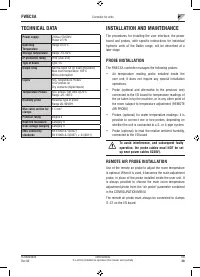
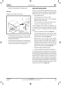
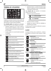
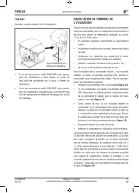
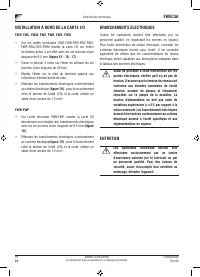
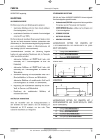
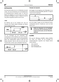
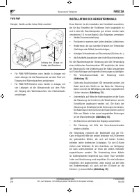
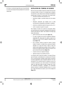
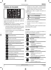
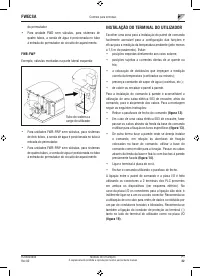
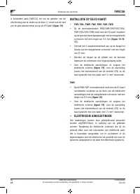
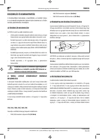
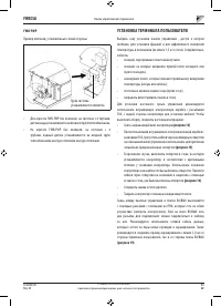
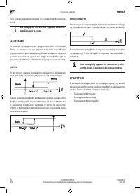
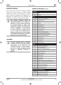
USER UNIT INSTALLATION
Choose an area to install the controller panel which is easily
accessible to set functions and efficient for room temperature
detection (at least 1.5 m from the floor). Therefore, avoid:
•
direct sunlight exposure;
•
direct exposure to hot or cold air currents;
•
placing obstacles which impair correct temperature
detection (cur tains or furniture);
•
the constant presence of water vapour (kitchens, etc.):
•
covering or recessing the panel into the wall.
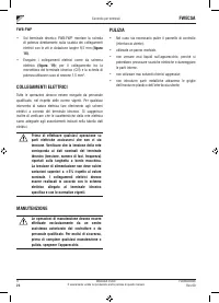
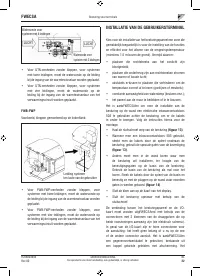
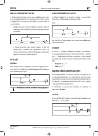
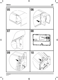
For wall installation of the controller, it is advisable to use
a recessed 503 electrical contact box behind the controller
to house the wires. For installation, follow the instructions
below:
•
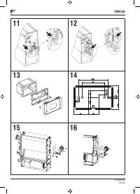
Remove the controller's closing screw
(figure 13)
.
•
If a 503 enclosed gang box is used, pass the cables
through the slot at the bottom of the controller and use
the relative holes for fastening
(figure 13)
.
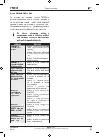
•
Otherwise drill a hole in the wall, for the fastening
holes on the base of the controller, where you wish to
install the controller. Use the base of the controller as
a template to mark the position of the holes. Pass the
cables through the slots on the base and fasten it with
plugs onto the previously drilled wall
(figure 14)
.
•
Connect the clamp to the display board.
•
Close the controller back up using the closing screw.
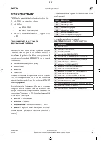
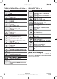
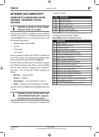
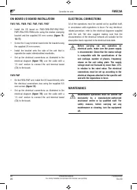
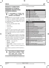
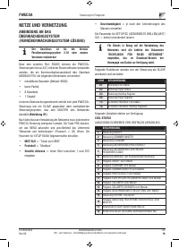
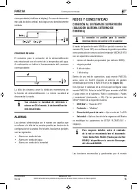
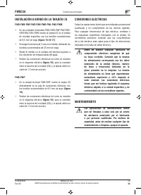
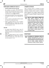
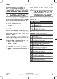
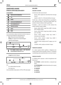
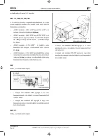
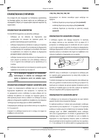
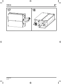
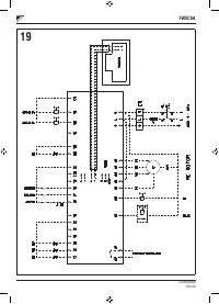
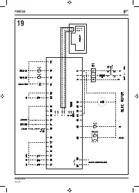
The connection between the panel and the controller and
the I/O board must be set up using the 2-clamp connectors
for conveyed waves installed on both devices (see electrical
diagram). With the I/O board, there are 2 connectors to set
up the connection: it makes no difference which connector is
used. It is necessary to use a data cable for networks with a
pair of twisted conductors and shielding. It is also necessary
to connect the shielding conductor to the clamp (-) on the
user side and on the I/O board
(figure 19)
.
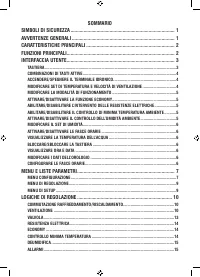
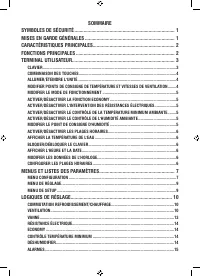
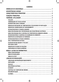
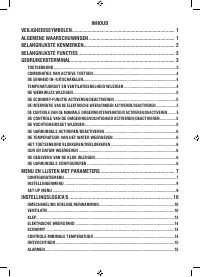
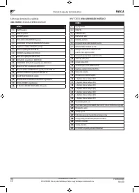
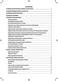
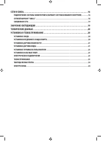
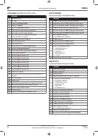
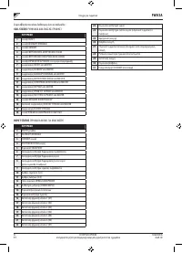
Содержание
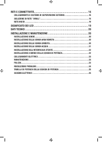
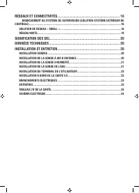
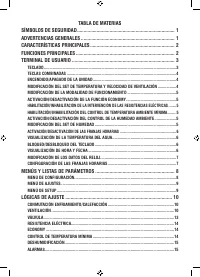
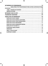
- 218 СЕТИ И СВЯЗЬ ��������������������������������������������������������������������������������������������������������16
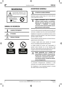
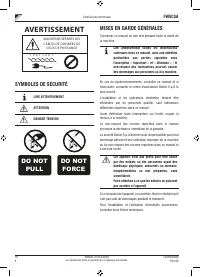
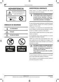
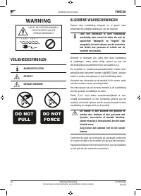
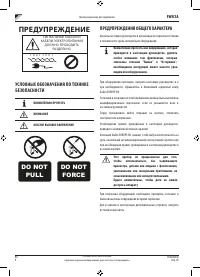
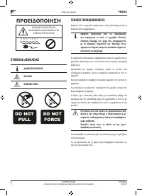
- 219 ПРЕДУПРЕЖДЕНИЕ; УСЛОВНЫЕ ОБОЗНАЧЕНИЯ ПО ТЕХНИКЕ; ВНИМАТЕЛЬНО ПРОЧЕСТЬ; ПРЕДУПРЕЖДЕНИЯ ОБЩЕГО ХАРАКТЕРА
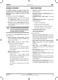
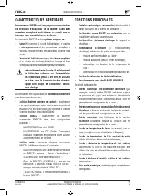
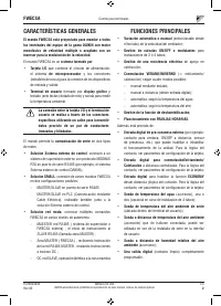
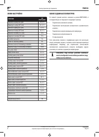
- 220 Основные характеристики
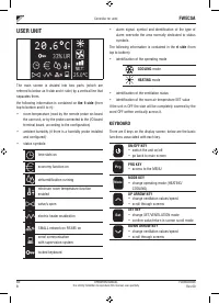
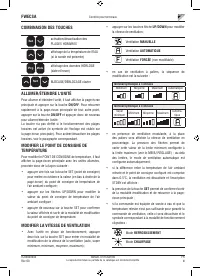
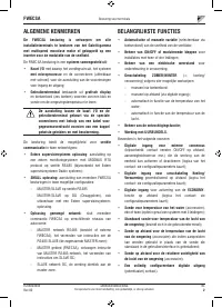
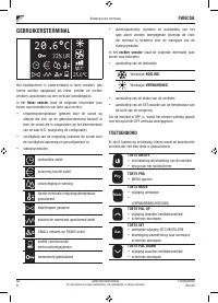
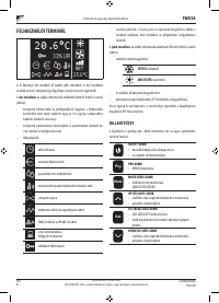
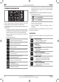
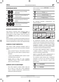
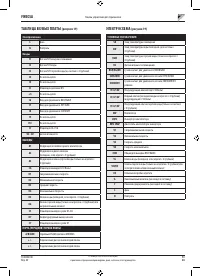
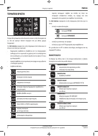
- 221 ТЕРМИНАЛ ПОЛЬЗОВАТЕЛЯ; КЛАВИАТУРА
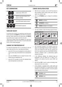
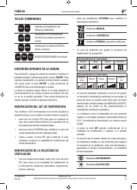
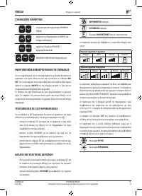
- 222 ВКЛЮЧИТЬ ВЫКЛЮЧИТЬ АГРЕГАТ
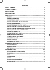
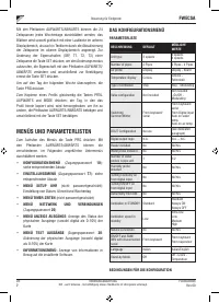
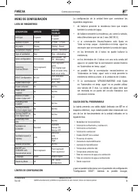
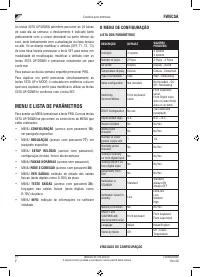
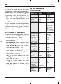
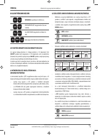
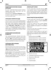
- 225 МЕНЮ И СПИСКИ ПАРАМЕТРОВ; МЕНЮ КОНФИГУРАЦИИ
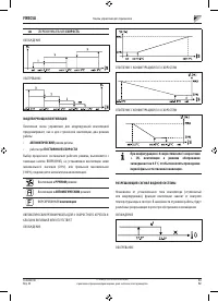
- 226 ЦИФРОВОЙ КОНФИГУРИРУЕМЫЙ ВЫХОД; НР
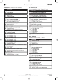
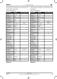
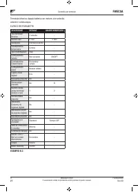
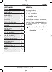
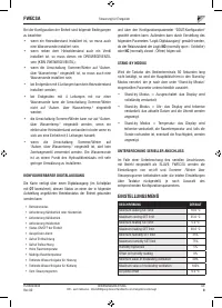
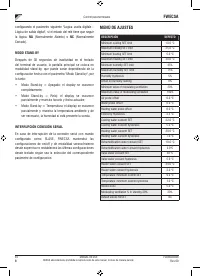
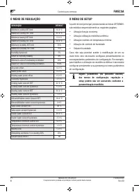
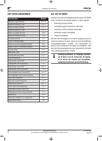
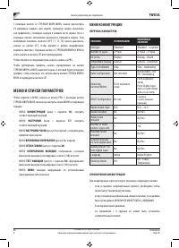
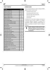
- 227 МЕНЮ ЗАДАННЫХ ПАРАМЕТРОВ
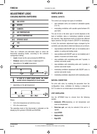
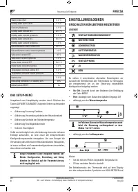
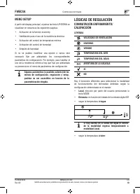
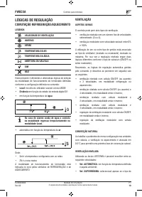
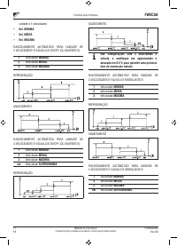
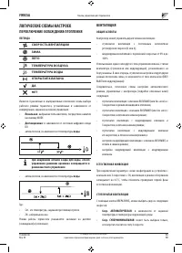
- 228 ЛОГИЧЕСКИЕ СХЕМЫ НАСТРОЕК; ПЕРЕКЛЮЧЕНИЕ ОХЛАЖДЕНИЯ/ОТОПЛЕНИЯ
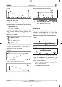
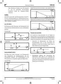
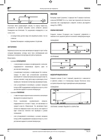
- 231 ФОРСИРОВКИ; КЛАПАН; МОДУЛИРУЮЩИЙ КЛАПАН
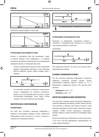
- 232 РАЗРЕШАЮЩИЙ СИГНАЛ ВОДНОЙ СИСТЕМЫ; ЭЛЕКТРИЧЕСКОЕ СОПРОТИВЛЕНИЕ; АКТИВИРОВАНИЕ; КОНТРОЛЬ МИНИМАЛЬНОЙ ТЕМПЕРАТУРЫ
- 233 ОС УШЕНИЕ; ЛОГИЧЕСКАЯ СХЕМА; СИГНАЛЫ ТРЕВОГИ
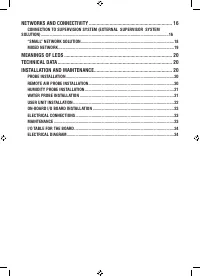
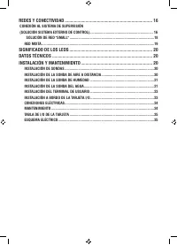
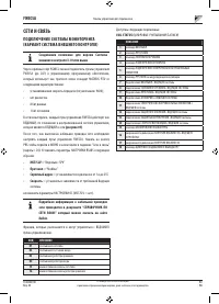
- 234 СЕТИ И СВЯЗЬ; ПОДКЛЮЧЕНИЕ СИСТЕМЫ МОНИТОРИНГА; Протокол
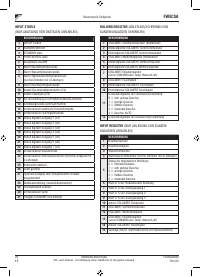
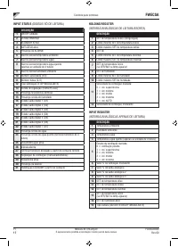
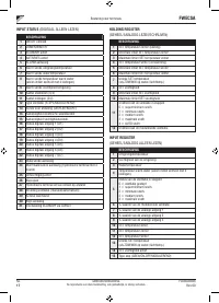
- 235 СТАТУС ВХОДА; РЕГИСТР ХРАНЕНИЯ; ВХОД РЕГИСТРА
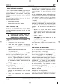
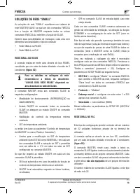
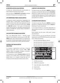
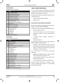
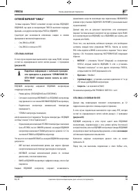
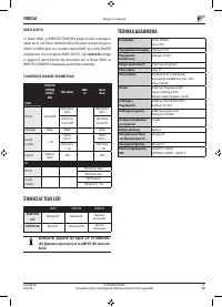
- 236 СЕТЕВОЙ ВАРИАНТ “SMALL”
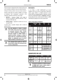
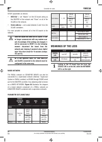
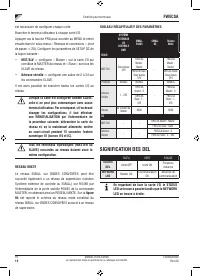
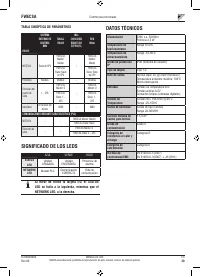
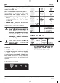
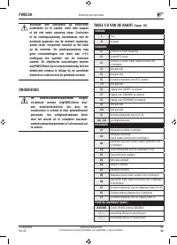
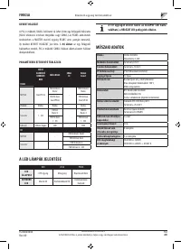
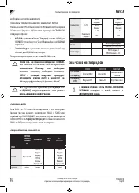
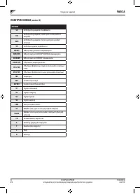
- 237 Серийный адрес; СМЕШЕННАЯ СЕТЬ; СВОДНАЯ ТАБЛИЦА ПАРАМЕТРОВ; ЗНАЧЕНИЕ СВЕТОДИОДОВ
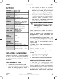
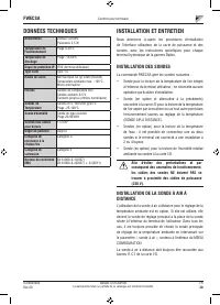
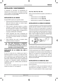
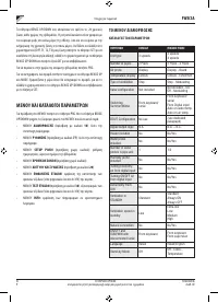
- 238 ТЕХНИЧЕСКИЕ ДАННЫЕ; УСТАНОВКА И ТЕХОБСЛУЖИВАНИЕ; УСТАНОВКА ЗОНДА; УСТАНОВКА УДАЛЕННОГО ДАТЧИКА ВОЗДУХА
- 240 УСТАНОВКА ТЕРМИНАЛА ПОЛЬЗОВАТЕЛЯ
- 241 ПОДКЛЮЧЕНИЯ ЭЛЕКТРОСИСТЕМЫ
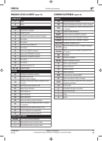
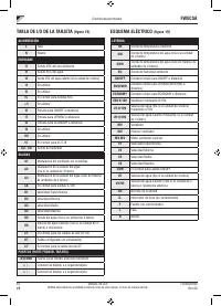
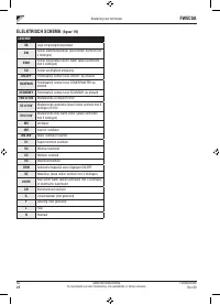
- 242 ЭЛЕКТРОСХЕМА


