Кондиционеры Daikin FWP-AT - инструкция пользователя по применению, эксплуатации и установке на русском языке. Мы надеемся, она поможет вам решить возникшие у вас вопросы при эксплуатации техники.
Если остались вопросы, задайте их в комментариях после инструкции.
"Загружаем инструкцию", означает, что нужно подождать пока файл загрузится и можно будет его читать онлайн. Некоторые инструкции очень большие и время их появления зависит от вашей скорости интернета.


FC66003946
Rev 00
USER MANUAL
It is strictly forbidden to reproduce this manual, even par tially
EN
20
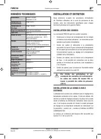
FWECSA
Controller for units
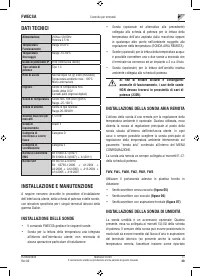
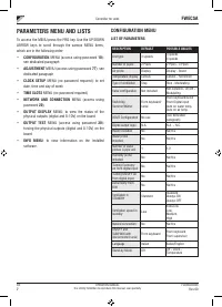
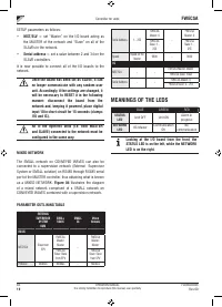
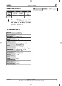
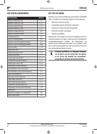
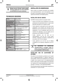
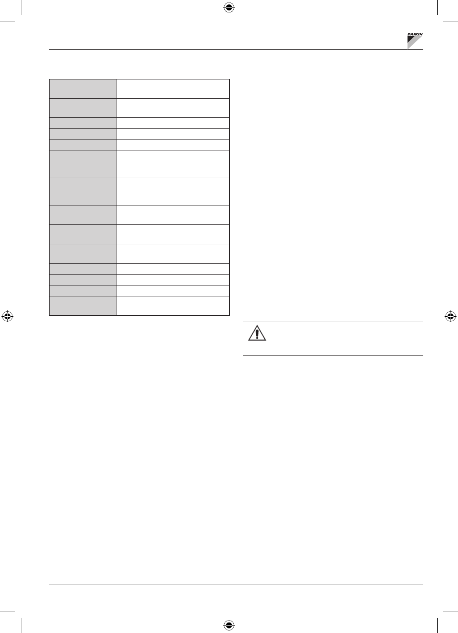
TECHNICAL DATA
Power supply
230Vac 50/60Hz
Power 2.5 W
Operating
Temperature
Range 0-50°C
Storage Temperature
Range -10-60°C
IP protection rating
IP30 (user unit)
Type of board
Type 1.C
Output relay
Normal Open 5A @ 240V (Resistive)
Max room temperature: 105°C
Micro-interruption
Inputs
NTC Temperature Probes
0-5V probes on
Dry contacts (digital inputs)
Temperature Probes
NTC probes 10K Ohm @25°C
Range -25-100°C
Humidity probe
Resistive type of probe
Range 20-90%RH
Max cable section for
clamps
1.5 mm
2
Pollution rating
Degree II
Heat/fire resistance
Category D
Over-voltage category
Category II
EMC conformity
standards
EN 61000-6-1(2007)
EN 61000-6-3(2007) + A1(2011)
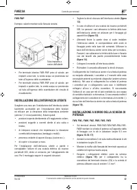
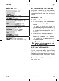
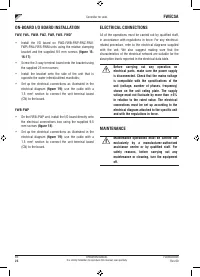
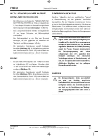
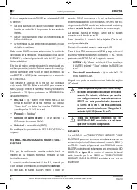
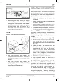
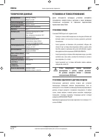
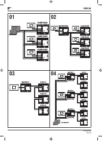
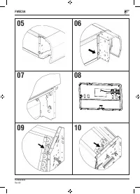
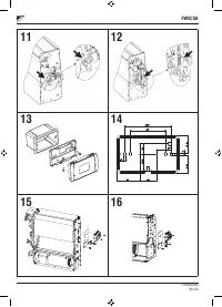
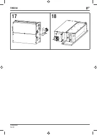
INSTALLATION AND MAINTENANCE
The procedures for installing the user interface, the power
board and probes, with specific instructions for individual
hydronic units of the Daikin range, will be described at a
later stage.
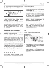
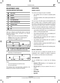
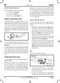
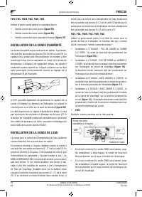
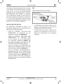
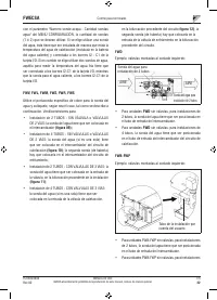
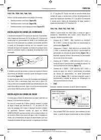
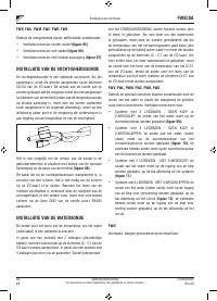
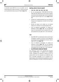
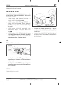
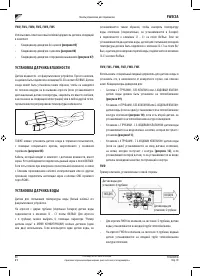
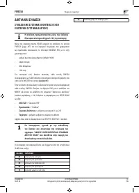
PROBE INSTALLATION
The FWECSA controller manages the following probes:
•
Air temperature reading probe installed inside the
user unit; it does not require any special installation
operations.
•
Probe (optional and alternative to the previous one)
connected to the I/O board for temperature readings of
the air taken in by the machine, or in any other point of
the room subject to temperature adjustment (REMOTE
AIR PROBE)
•
Probes (optional) for water temperature readings: it is
possible to connect one or two probes, depending on
whether the unit is connected to a 2- or 4-pipe system.
•
Probe (optional) to read the relative ambient humidity,
connected to the I/O board
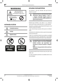
To avoid interference, and subsequent faulty
operation, the probe cables must NOT be set
up near power cables 8230V).
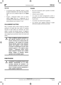
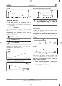
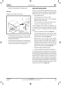
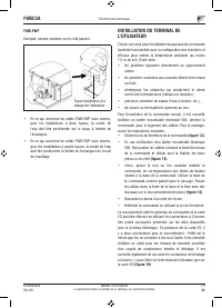
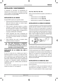
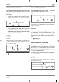
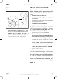
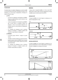
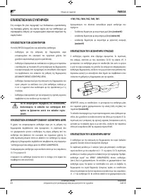
REMOTE AIR PROBE INSTALLATION
Use of the remote air probe to adjust the room temperature
is optional. When it is used, it becomes the main adjustment
probe, in place of the probe installed inside the user unit. It
is always possible to choose the main room temperature
adjustment probe from the "air probe" parameter contained
in the CONFIGURATION MENU.
The remote air probe must always be connected to clamps
I1-C1 on the I/O board.
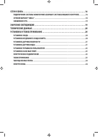
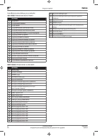
Содержание
- 218 СЕТИ И СВЯЗЬ ��������������������������������������������������������������������������������������������������������16
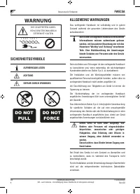
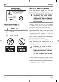
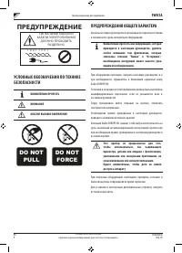
- 219 ПРЕДУПРЕЖДЕНИЕ; УСЛОВНЫЕ ОБОЗНАЧЕНИЯ ПО ТЕХНИКЕ; ВНИМАТЕЛЬНО ПРОЧЕСТЬ; ПРЕДУПРЕЖДЕНИЯ ОБЩЕГО ХАРАКТЕРА
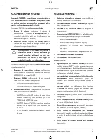
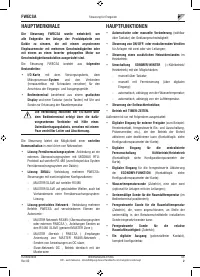
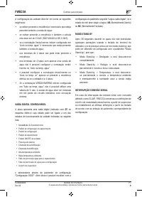
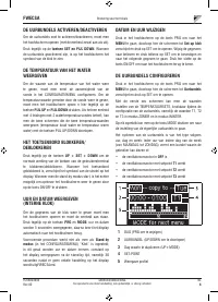
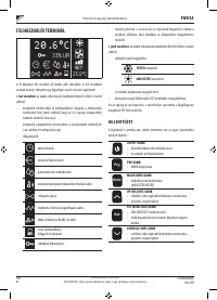
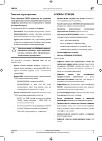
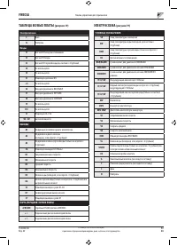
- 220 Основные характеристики
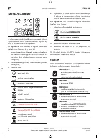
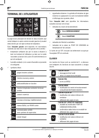
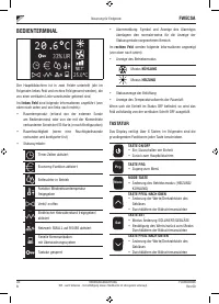
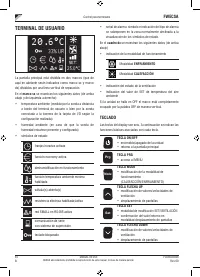
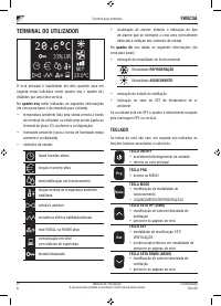
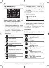
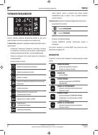
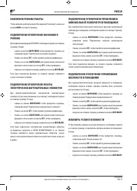
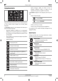
- 221 ТЕРМИНАЛ ПОЛЬЗОВАТЕЛЯ; КЛАВИАТУРА
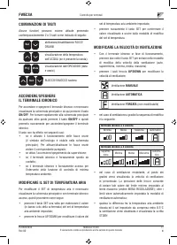
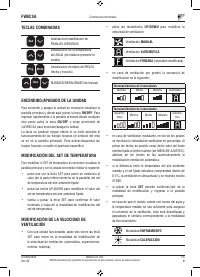
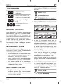
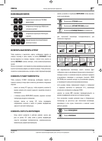
- 222 ВКЛЮЧИТЬ ВЫКЛЮЧИТЬ АГРЕГАТ
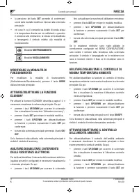
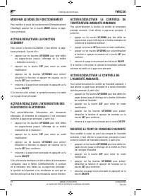
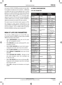
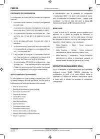
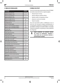
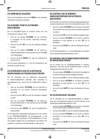
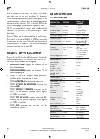
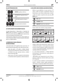
- 225 МЕНЮ И СПИСКИ ПАРАМЕТРОВ; МЕНЮ КОНФИГУРАЦИИ
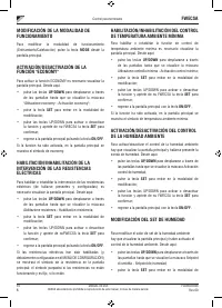
- 226 ЦИФРОВОЙ КОНФИГУРИРУЕМЫЙ ВЫХОД; НР
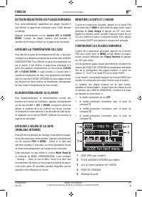
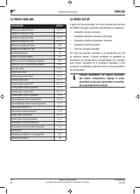
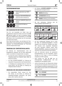
- 227 МЕНЮ ЗАДАННЫХ ПАРАМЕТРОВ
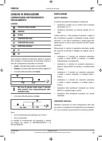
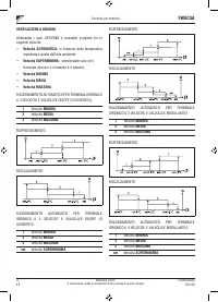
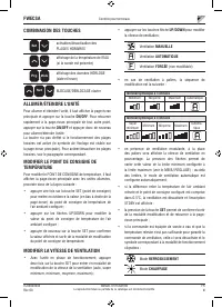
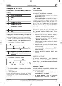
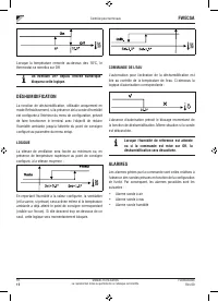
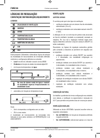
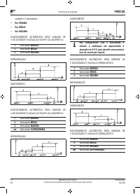
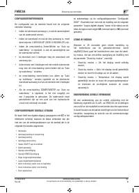
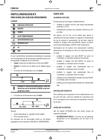
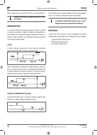
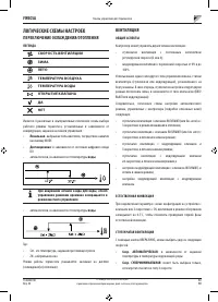
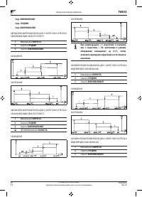
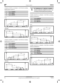
- 228 ЛОГИЧЕСКИЕ СХЕМЫ НАСТРОЕК; ПЕРЕКЛЮЧЕНИЕ ОХЛАЖДЕНИЯ/ОТОПЛЕНИЯ
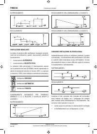
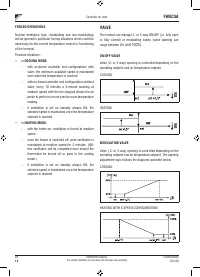
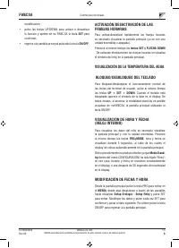
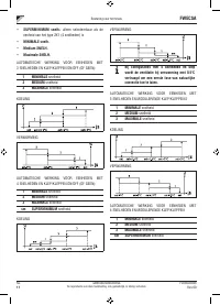
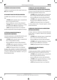
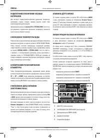
- 231 ФОРСИРОВКИ; КЛАПАН; МОДУЛИРУЮЩИЙ КЛАПАН
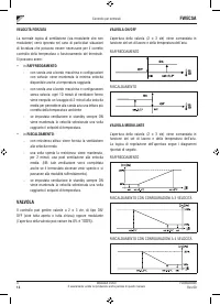
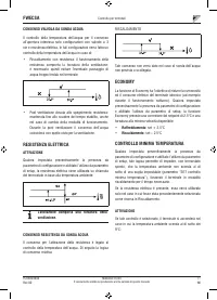
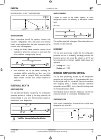
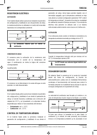
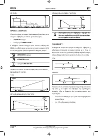
- 232 РАЗРЕШАЮЩИЙ СИГНАЛ ВОДНОЙ СИСТЕМЫ; ЭЛЕКТРИЧЕСКОЕ СОПРОТИВЛЕНИЕ; АКТИВИРОВАНИЕ; КОНТРОЛЬ МИНИМАЛЬНОЙ ТЕМПЕРАТУРЫ
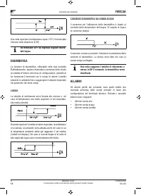
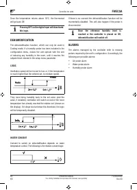
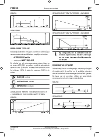
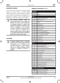
- 233 ОС УШЕНИЕ; ЛОГИЧЕСКАЯ СХЕМА; СИГНАЛЫ ТРЕВОГИ
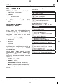
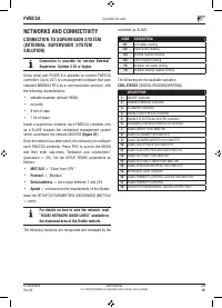
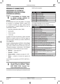
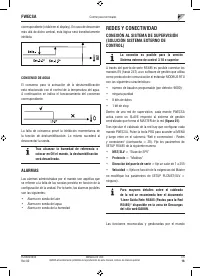
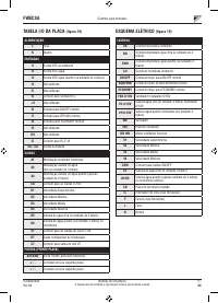
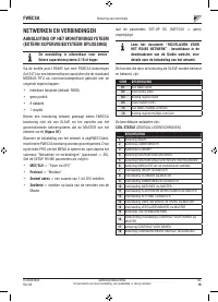
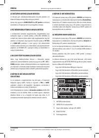
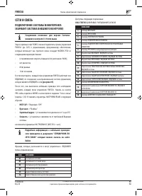
- 234 СЕТИ И СВЯЗЬ; ПОДКЛЮЧЕНИЕ СИСТЕМЫ МОНИТОРИНГА; Протокол
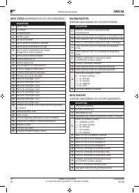
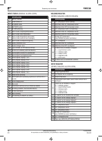
- 235 СТАТУС ВХОДА; РЕГИСТР ХРАНЕНИЯ; ВХОД РЕГИСТРА
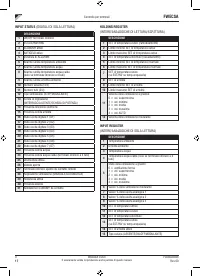
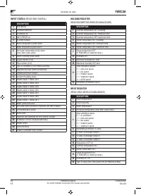
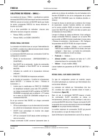
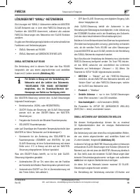
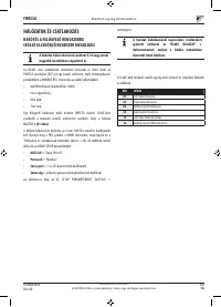
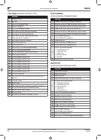
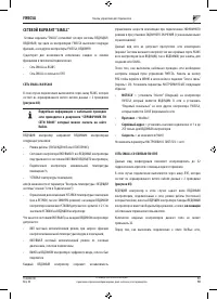
- 236 СЕТЕВОЙ ВАРИАНТ “SMALL”
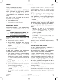
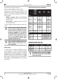
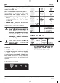
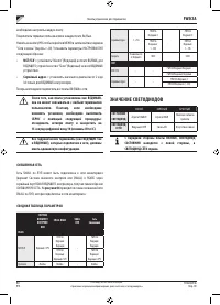
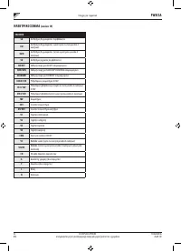
- 237 Серийный адрес; СМЕШЕННАЯ СЕТЬ; СВОДНАЯ ТАБЛИЦА ПАРАМЕТРОВ; ЗНАЧЕНИЕ СВЕТОДИОДОВ
- 238 ТЕХНИЧЕСКИЕ ДАННЫЕ; УСТАНОВКА И ТЕХОБСЛУЖИВАНИЕ; УСТАНОВКА ЗОНДА; УСТАНОВКА УДАЛЕННОГО ДАТЧИКА ВОЗДУХА
- 240 УСТАНОВКА ТЕРМИНАЛА ПОЛЬЗОВАТЕЛЯ
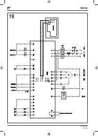
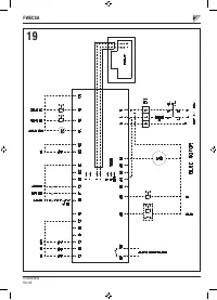
- 241 ПОДКЛЮЧЕНИЯ ЭЛЕКТРОСИСТЕМЫ
- 242 ЭЛЕКТРОСХЕМА


