Кондиционеры Daikin FWP-AT - инструкция пользователя по применению, эксплуатации и установке на русском языке. Мы надеемся, она поможет вам решить возникшие у вас вопросы при эксплуатации техники.
Если остались вопросы, задайте их в комментариях после инструкции.
"Загружаем инструкцию", означает, что нужно подождать пока файл загрузится и можно будет его читать онлайн. Некоторые инструкции очень большие и время их появления зависит от вашей скорости интернета.


EN
21
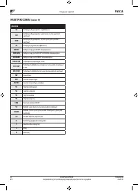
OPERATION MANUAL
It is strictly forbidden to reproduce this manual, even par tially
FC66003946
Rev 00
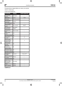
Controller for units
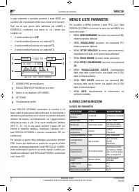
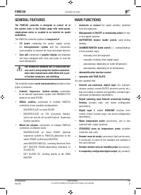
FWECSA
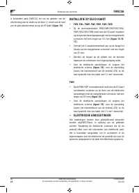
FWV, FWL, FWM, FWZ, FWR, FWS
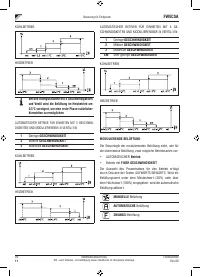
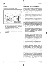
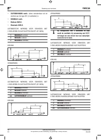
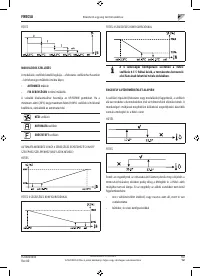
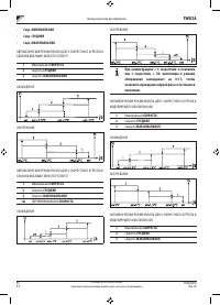
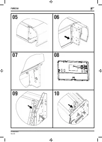
Use the supplied adhesive plastic probe-holder:
•
Fan coil without base
(figure 05)
•
Fan coil with base
(figure 06)
•
Fan coil with front suction
(figure 07)
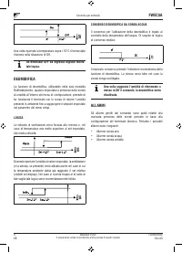
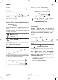
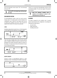
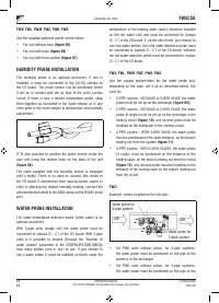
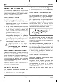
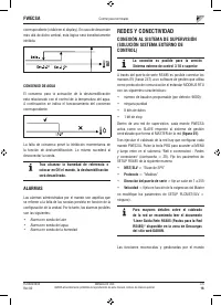
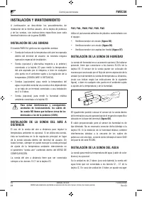
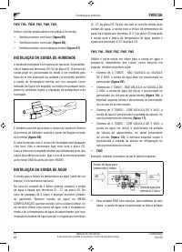
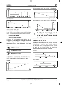
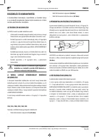
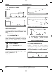
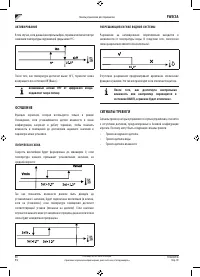
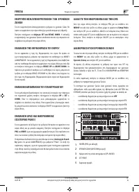
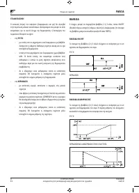
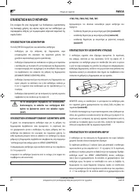
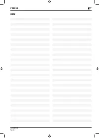
HUMIDITY PROBE INSTALLATION
The humidity probe is an optional accessory. If one is
installed, it must be connected to the SU-SU clamps on
the I/O board. The probe sensor can be positioned where
it will be in contact with the air flow of the unit's suction
circuit (if there is also a remote temperature probe, strap
them together as illustrated in the figure below) or in any
other point in the room subject to temperature and humidity
adjustment.
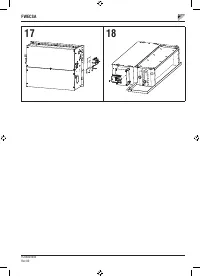
IT IS also possible to position the probe sensor inside the
user unit using the relative hook on the base of the unit
(figure 08)
.
The cable supplied with the humidity sensor is equipped
with a shield. There is no need to connect this shield to
the I/O board. If interference from near-by power cables or
other is affecting the relative humidity reading, connect the
aforementioned shield to the GND clamp on the RS485 serial
por t.
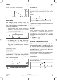
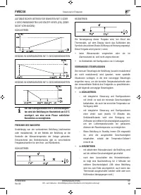
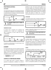
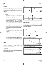
WATER PROBE INSTALLATION
The water temperature detection probe (white cable) is an
optional accessory.
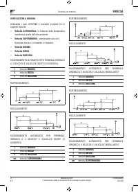
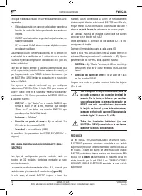
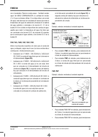
With 2-pipe units (single coil) the water probe must be
connected to clamps I2 - C1 of the I/O board. With 4-pipe
units it is possible to choose (through the "Number of
water probes" parameter in the CONFIGURATION MENU)
how many probes (one or two) to use. If you choose to
use a water probe, it must be installed so that it reads the
temperature of the heating water (and is therefore installed
on the hot water coil) and must be connected to clamps
I2 - C1 of the I/O board. If, on the other hand, you choose to
use two water probes, the cold water detection probe must
be connected to clamps I2 - C1 of the I/O board, whereas
the hot water detection probe must be connected to clamps
I3 - C1 of the I/O board.
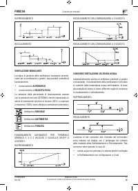
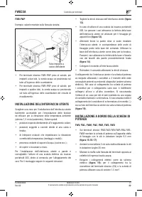
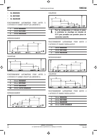
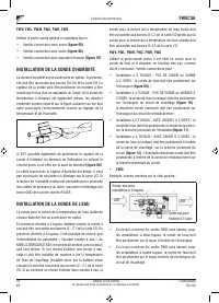
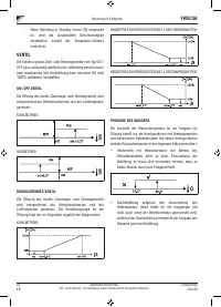
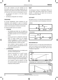
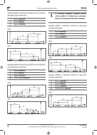
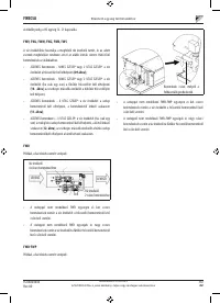
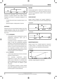
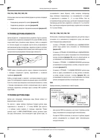
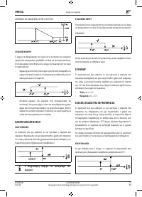
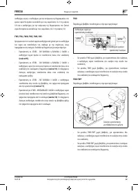
FWV, FWL, FWM, FWZ, FWR, FWS
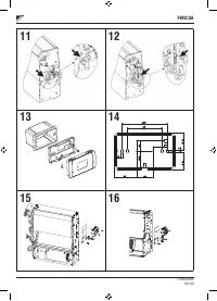
Use the copper probe-holder for the water probe and,
depending on the case, set it up as described below. Fan
coils for:
•
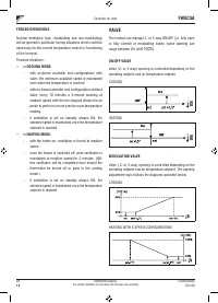
2-PIPE system - NO VALVE or 2-WAY VALVE: the water
probe must be set up on the exchanger
(figure 09);
•
2-PIPE system - NO VALVE or 2-WAY VALVE: the water
probe (if single) must be set up on the exchanger in the
heating circuit
(figure 10)
; any second probe must be
installed on the exchanger in the cooling circuit;
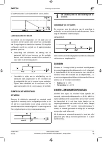
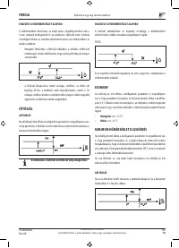
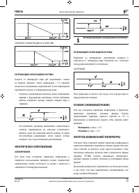
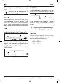
•
2-PIPE system - WITH 3-WAY VALVE: the water probe
must be positioned on the valve entrance, on the branch
leading out from the system
(figure 11)
;
•
4-PIPE system - WITH 3-WAY VALVES: the water probe
(if single) must be positioned on the entrance of the
heating valve, on the branch leading out from the circuit
(figure 12)
; any second probe must be installed on the
entrance of the cooling valve on the branch leading out
from the circuit.
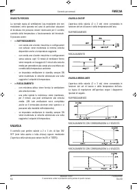
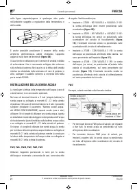
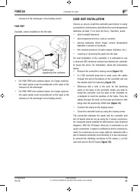
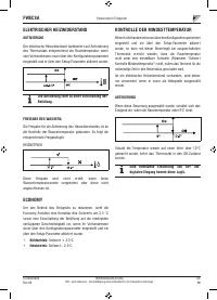
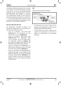
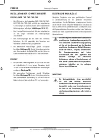
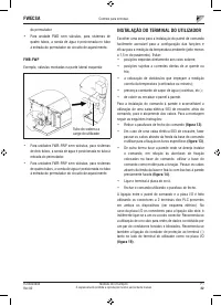
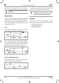
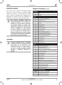
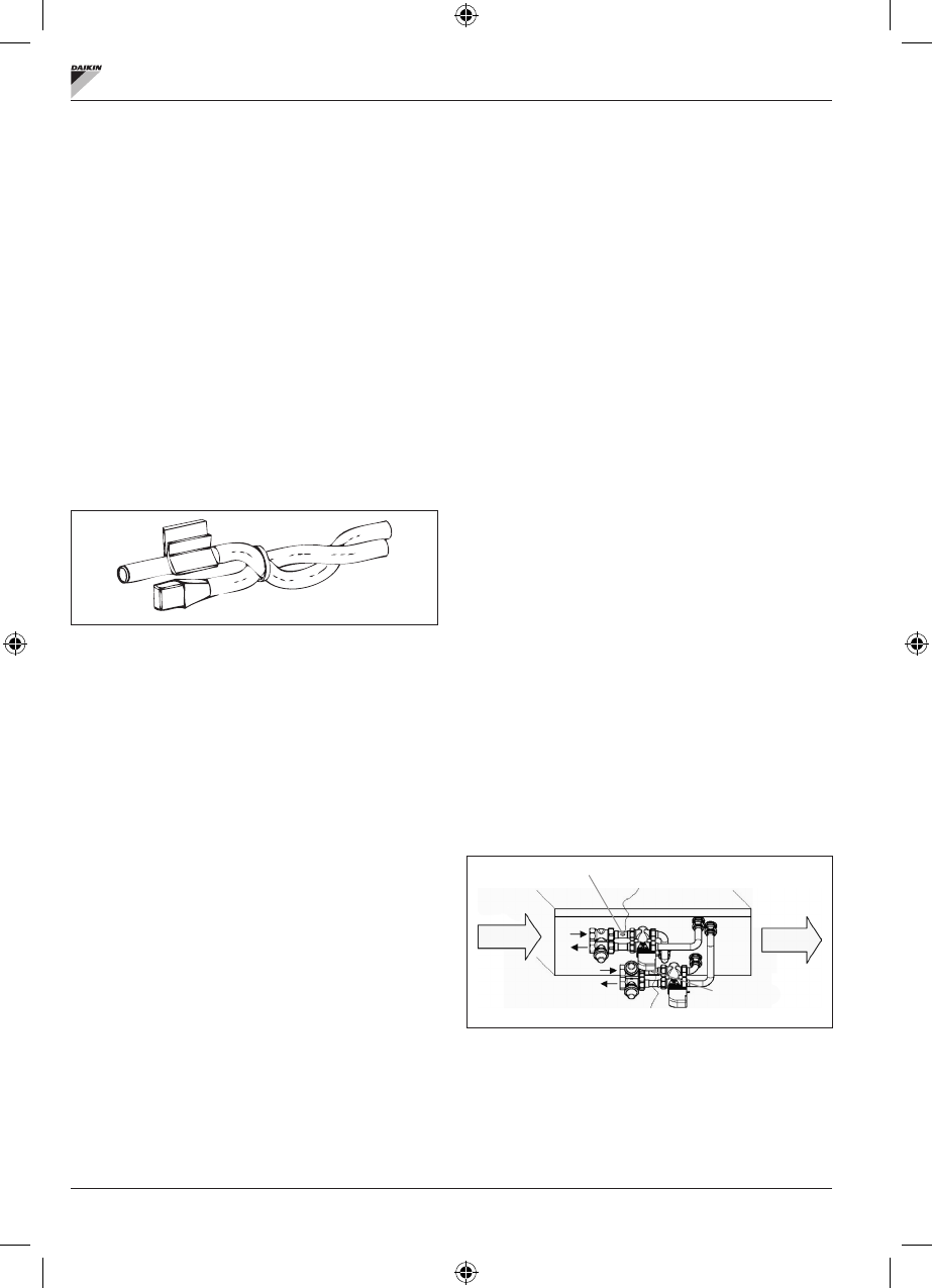
FWD
Example, valves installed on the left side:
Water probe for
2-pipe system
Water probe for
4-pipe system
AIR
AIR
•
For FWD units without valves, for 2-pipe systems,
the water probe must be positioned on the pipe at the
entrance of the exchanger.
•
For FWD units without valves, for 4-pipe systems,
the water probe must be positioned on the pipe at the
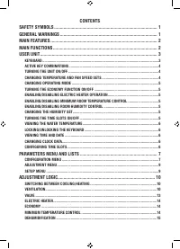
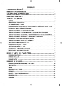
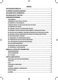
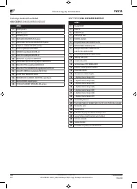
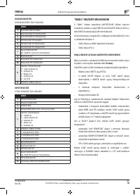
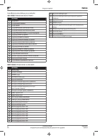
Содержание
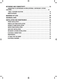
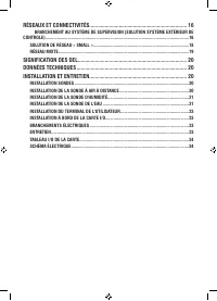
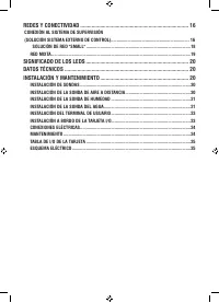
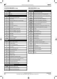
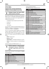
- 218 СЕТИ И СВЯЗЬ ��������������������������������������������������������������������������������������������������������16
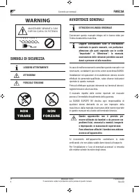
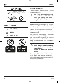
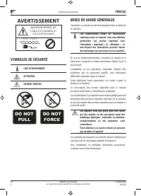
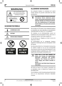
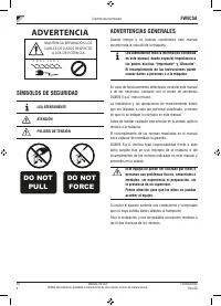
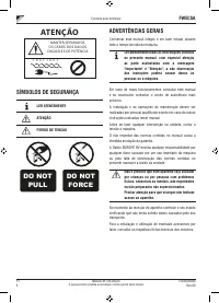
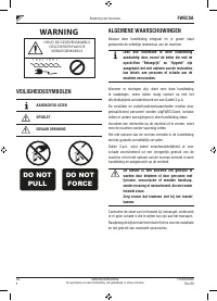
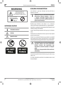
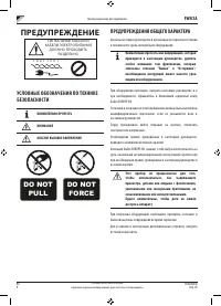
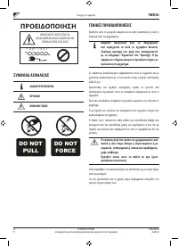
- 219 ПРЕДУПРЕЖДЕНИЕ; УСЛОВНЫЕ ОБОЗНАЧЕНИЯ ПО ТЕХНИКЕ; ВНИМАТЕЛЬНО ПРОЧЕСТЬ; ПРЕДУПРЕЖДЕНИЯ ОБЩЕГО ХАРАКТЕРА
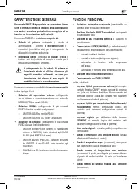
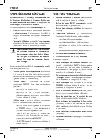
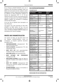
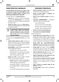
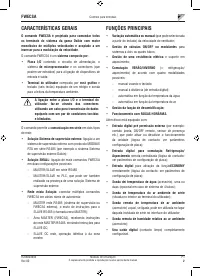
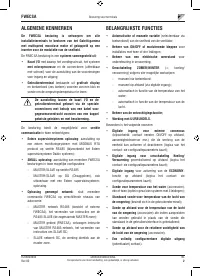
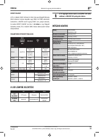
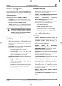
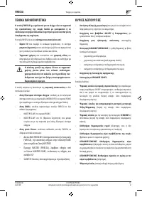
- 220 Основные характеристики
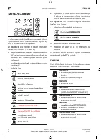
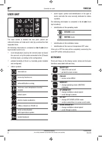
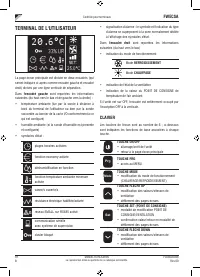
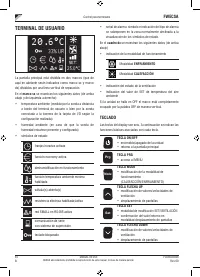
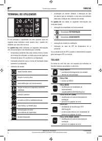
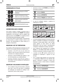
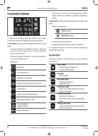
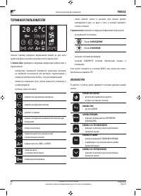
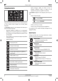
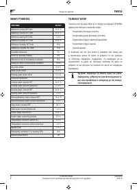
- 221 ТЕРМИНАЛ ПОЛЬЗОВАТЕЛЯ; КЛАВИАТУРА
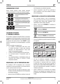
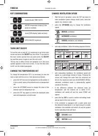
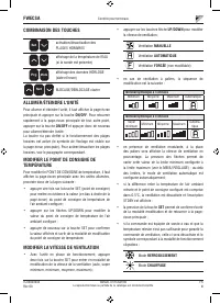
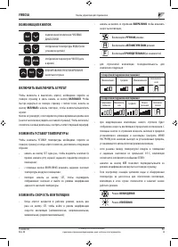
- 222 ВКЛЮЧИТЬ ВЫКЛЮЧИТЬ АГРЕГАТ
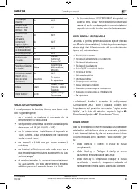
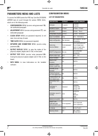
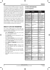
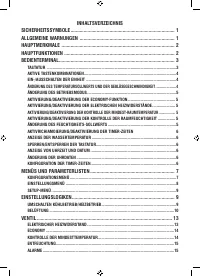
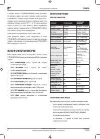
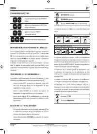
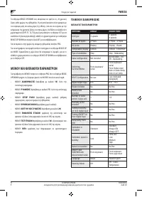
- 225 МЕНЮ И СПИСКИ ПАРАМЕТРОВ; МЕНЮ КОНФИГУРАЦИИ
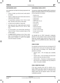
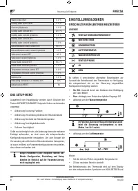
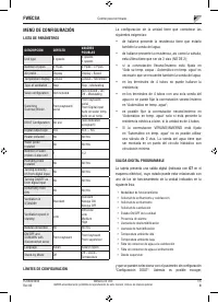
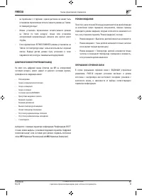
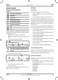
- 226 ЦИФРОВОЙ КОНФИГУРИРУЕМЫЙ ВЫХОД; НР
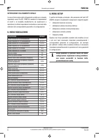
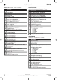
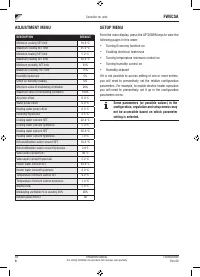
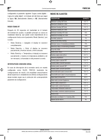
- 227 МЕНЮ ЗАДАННЫХ ПАРАМЕТРОВ
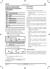
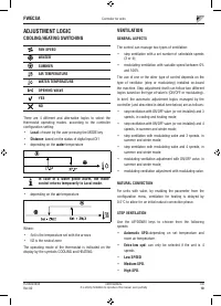
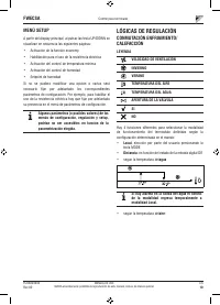
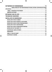
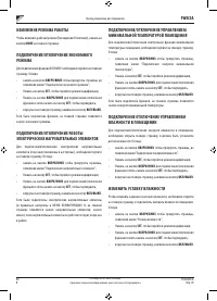
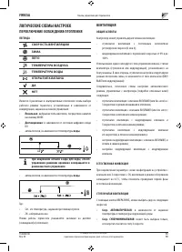
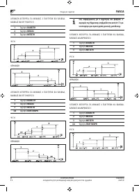
- 228 ЛОГИЧЕСКИЕ СХЕМЫ НАСТРОЕК; ПЕРЕКЛЮЧЕНИЕ ОХЛАЖДЕНИЯ/ОТОПЛЕНИЯ
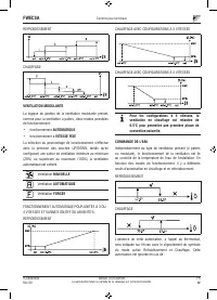
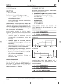
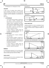
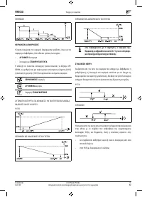
- 231 ФОРСИРОВКИ; КЛАПАН; МОДУЛИРУЮЩИЙ КЛАПАН
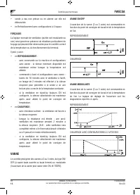
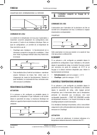
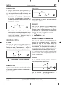
- 232 РАЗРЕШАЮЩИЙ СИГНАЛ ВОДНОЙ СИСТЕМЫ; ЭЛЕКТРИЧЕСКОЕ СОПРОТИВЛЕНИЕ; АКТИВИРОВАНИЕ; КОНТРОЛЬ МИНИМАЛЬНОЙ ТЕМПЕРАТУРЫ
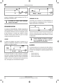
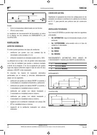
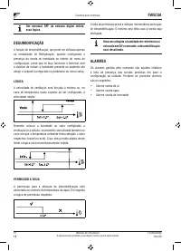
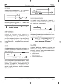
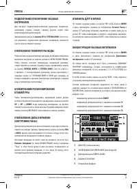
- 233 ОС УШЕНИЕ; ЛОГИЧЕСКАЯ СХЕМА; СИГНАЛЫ ТРЕВОГИ
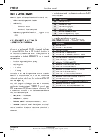
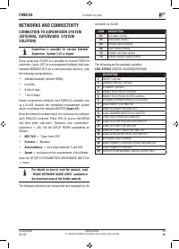
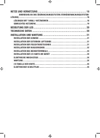
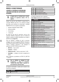
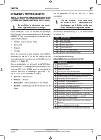
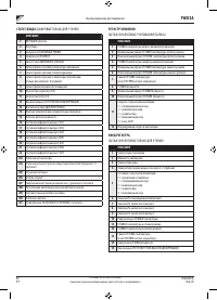
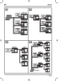
- 234 СЕТИ И СВЯЗЬ; ПОДКЛЮЧЕНИЕ СИСТЕМЫ МОНИТОРИНГА; Протокол
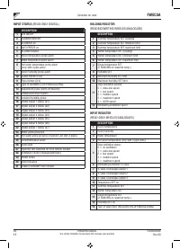
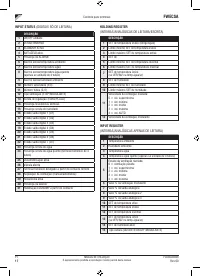
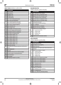
- 235 СТАТУС ВХОДА; РЕГИСТР ХРАНЕНИЯ; ВХОД РЕГИСТРА
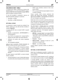
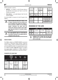
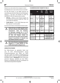
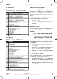
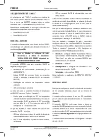
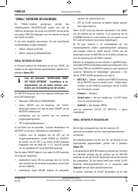
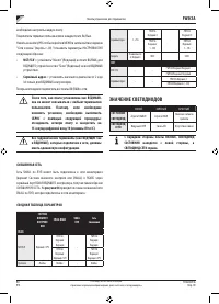
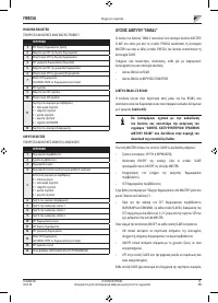
- 236 СЕТЕВОЙ ВАРИАНТ “SMALL”
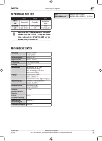
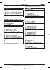
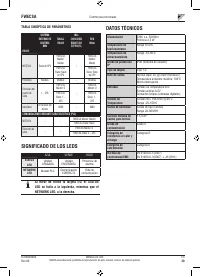
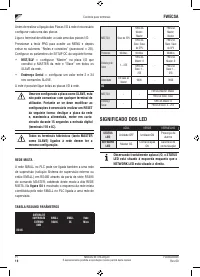
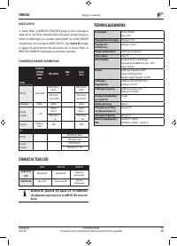
- 237 Серийный адрес; СМЕШЕННАЯ СЕТЬ; СВОДНАЯ ТАБЛИЦА ПАРАМЕТРОВ; ЗНАЧЕНИЕ СВЕТОДИОДОВ
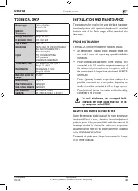
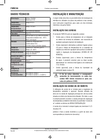
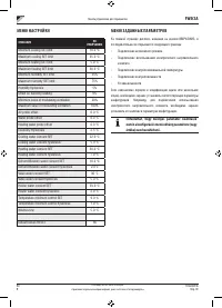
- 238 ТЕХНИЧЕСКИЕ ДАННЫЕ; УСТАНОВКА И ТЕХОБСЛУЖИВАНИЕ; УСТАНОВКА ЗОНДА; УСТАНОВКА УДАЛЕННОГО ДАТЧИКА ВОЗДУХА
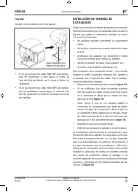
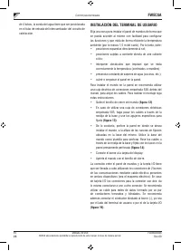
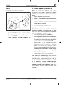
- 240 УСТАНОВКА ТЕРМИНАЛА ПОЛЬЗОВАТЕЛЯ
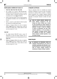
- 241 ПОДКЛЮЧЕНИЯ ЭЛЕКТРОСИСТЕМЫ
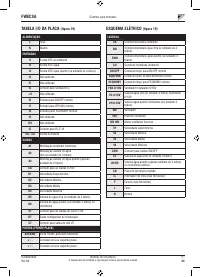
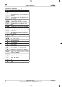
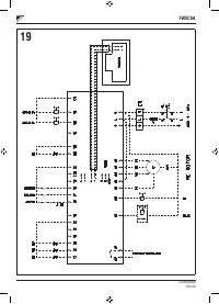
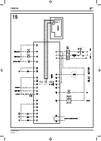
- 242 ЭЛЕКТРОСХЕМА


