Кондиционеры Daikin FWP-AT - инструкция пользователя по применению, эксплуатации и установке на русском языке. Мы надеемся, она поможет вам решить возникшие у вас вопросы при эксплуатации техники.
Если остались вопросы, задайте их в комментариях после инструкции.
"Загружаем инструкцию", означает, что нужно подождать пока файл загрузится и можно будет его читать онлайн. Некоторые инструкции очень большие и время их появления зависит от вашей скорости интернета.


FC66003946
Rev 00
USER MANUAL
It is strictly forbidden to reproduce this manual, even par tially
EN
2
FWECSA
Controller for units
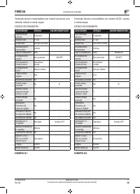
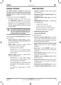
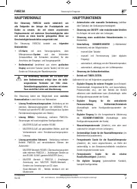
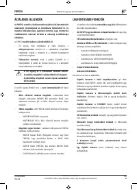
GENERAL FEATURES
The FWECSA controller is designed to control all of
the system units in the Daikin range with multi-speed,
single-phase motor or coupled to an inverter for speed
modulation
.
The FWECSA controller system is
composed of
:
•
I/O board
containing the power supply circuit,
the
microprocessor system
and the connectors
(unscrewable) to connect the input and output devices;
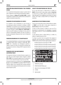
•
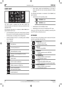
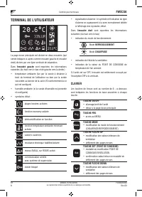
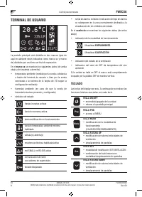
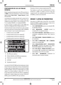
User unit
composed of
graphic display
and keyboard
(six keys) equipped with clock and probe to read the
room temperature.
The connection between the I/O board and the
user unit is set up using the relative connectors
and a data transmission cable fitted with a pair
of twisted conductors and shielding.
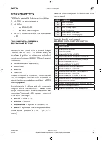
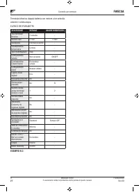
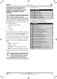
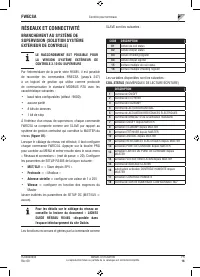
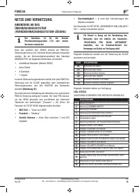
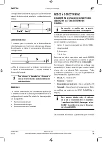
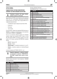
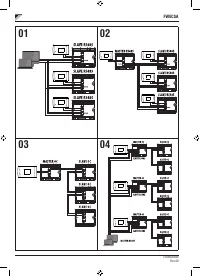
The controller makes
serial communication
possible on two
types of networks:
•
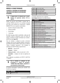
External Supervisor System solution
: connection
to an external supervision system with MODBUS RTU
protocol on serial RS485;
•
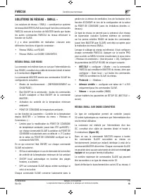
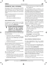
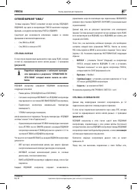
SMALL solution
: connection of multiple FWECSA
controllers in two possible configurations:
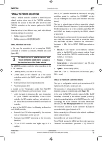
- MASTER/SLAVE on serial RS485
- MASTER/SLAVE on CW (Conveyed Waves),
which can also be set up with External Supervisor
System solutions.
•
Mixed net solution
: connection of multiple FWECSA
controllers on different levels :
- MASTER/SLAVE on serial RS485 (external
supervisor system or FWECSA),directions to the
slaves RS485 (called zone MASTER)
- zone MASTER FWECSA , receiving directions from
NET MASTER RS485,transmitting directions to
SLAVES OC
- NET SLAVES OC, working exactly to the ZONE
MASTER
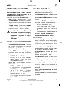
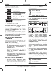
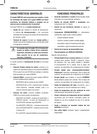
MAIN FUNCTIONS
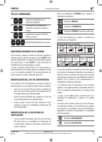
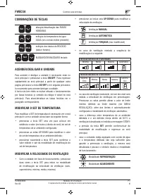
•
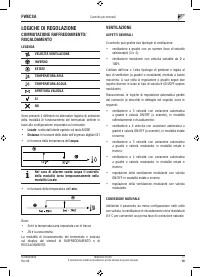
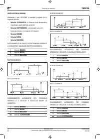
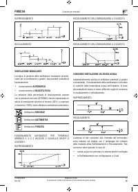
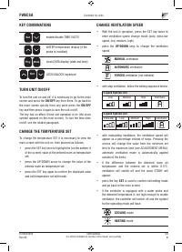
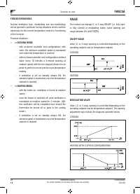
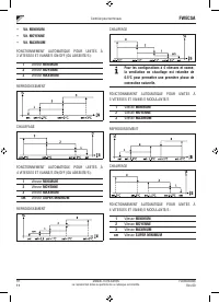
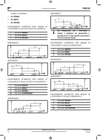
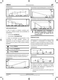
Automatic
or manual
fan speed variation (selected
from the keyboard);
•
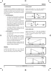
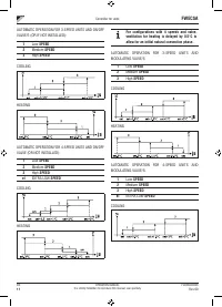
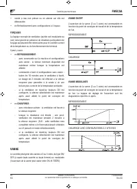
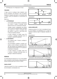
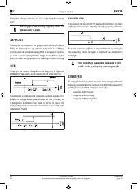
Management of ON/OFF or modulating valves
for two
or four-piped systems.
•
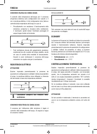
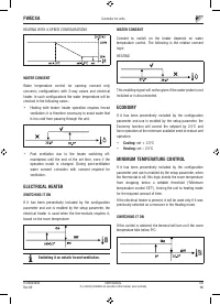
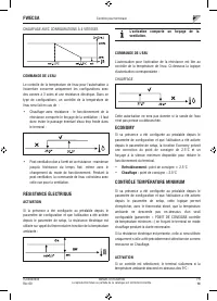
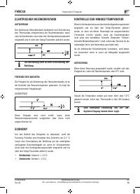
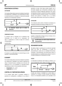
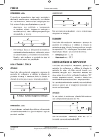
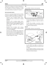
SUPPORTING electric heater control,
used during
heating;
•
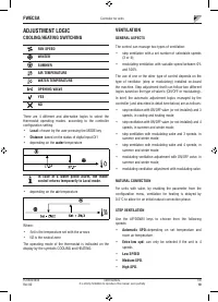
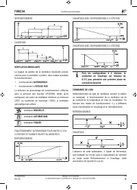
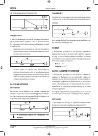
SUMMER/WINTER mode switch
(= cooling/heating)
in four possible ways:
- manually, from the keyboard;
- manually, remotely (from digital input);
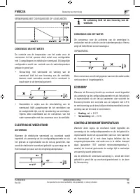
- automatically, depending on water temperature;
- automatically, depending on air temperature.
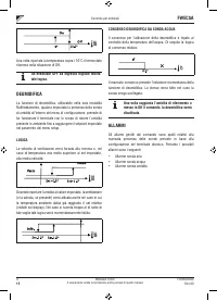
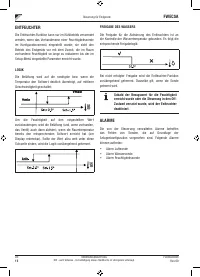
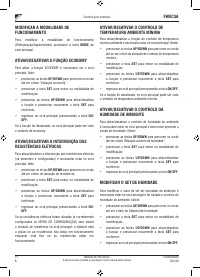
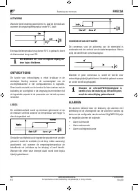
•
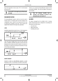
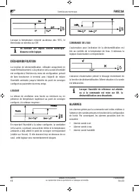
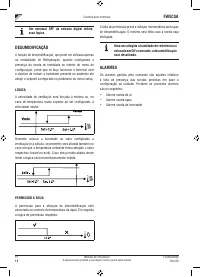
dehumidification function control;
•
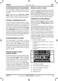
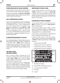
operation with TIME SLOTS.
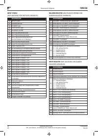
It is also supplied with:
•
External pre-consensus digital input
(for example:
window contact, remote ON/OFF, presence sensor, etc.)
that can enable or disable unit operation (contact logic:
see board configuration parameters);
•
Digital switching input
Remote centralised Cooling/
Heating
(contact logic: see board configuration
parameters);
•
Digital input
to enable
ECONOMY
function from
remote control (contact logic: see board configuration
parameters);
•
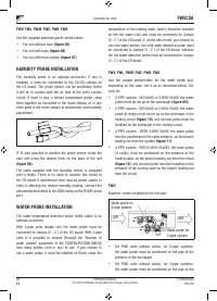
Water temperature probe
(accessory), one or two
(optional with 4-pipe systems);
•
STANDARD room air temperature probe
(installed
inside the user unit)
;
•
Remote room air probe
(accessory) that can be used,
if connected, in place of the standard one installed in
the user interface;
•
Remote relative room air humidity probe
(accessory);
•
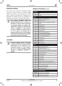
A completely configurable digital output
(dry contact).
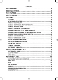
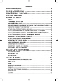
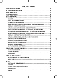
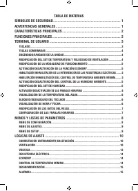
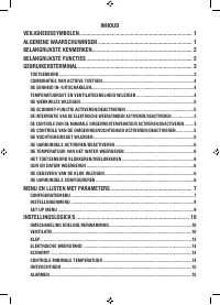
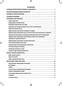
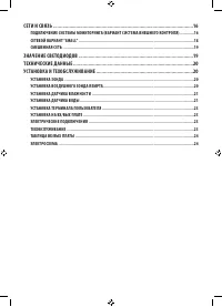
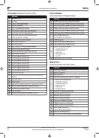
Содержание
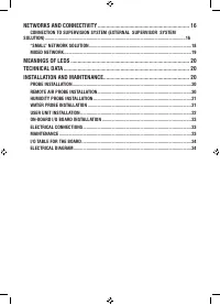
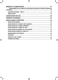
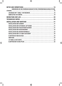
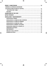
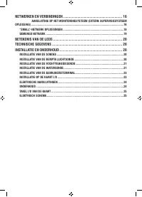
- 218 СЕТИ И СВЯЗЬ ��������������������������������������������������������������������������������������������������������16
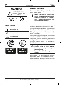
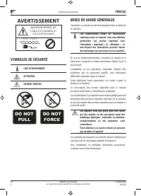
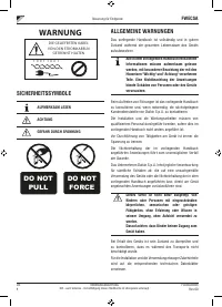
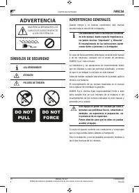
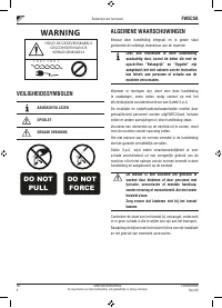
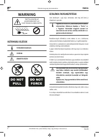
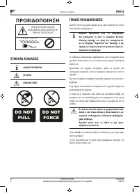
- 219 ПРЕДУПРЕЖДЕНИЕ; УСЛОВНЫЕ ОБОЗНАЧЕНИЯ ПО ТЕХНИКЕ; ВНИМАТЕЛЬНО ПРОЧЕСТЬ; ПРЕДУПРЕЖДЕНИЯ ОБЩЕГО ХАРАКТЕРА
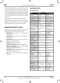
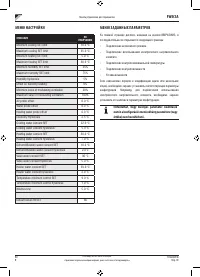
- 220 Основные характеристики
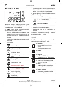
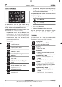
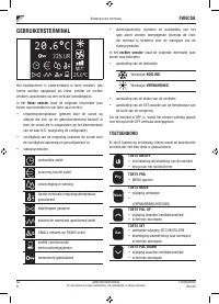
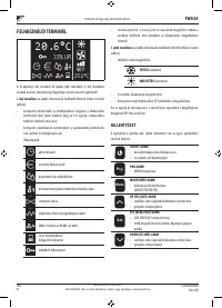
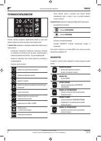
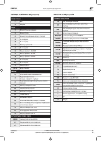
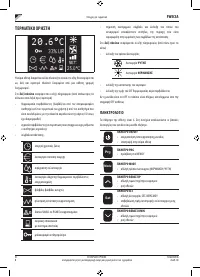
- 221 ТЕРМИНАЛ ПОЛЬЗОВАТЕЛЯ; КЛАВИАТУРА
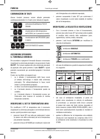
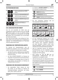
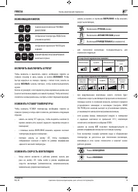
- 222 ВКЛЮЧИТЬ ВЫКЛЮЧИТЬ АГРЕГАТ
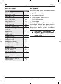
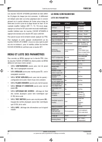
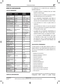
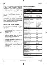
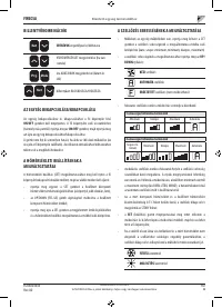
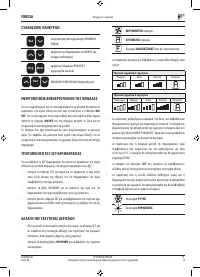
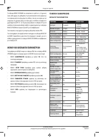
- 225 МЕНЮ И СПИСКИ ПАРАМЕТРОВ; МЕНЮ КОНФИГУРАЦИИ
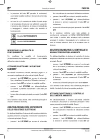
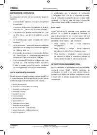
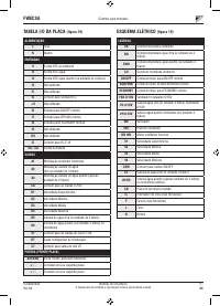
- 226 ЦИФРОВОЙ КОНФИГУРИРУЕМЫЙ ВЫХОД; НР
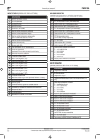
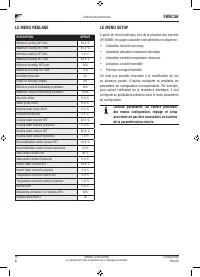
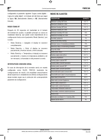
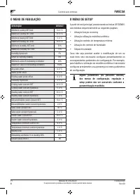
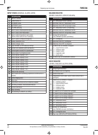
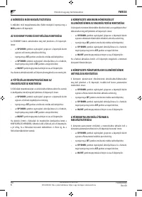
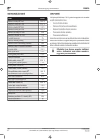
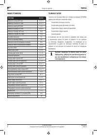
- 227 МЕНЮ ЗАДАННЫХ ПАРАМЕТРОВ
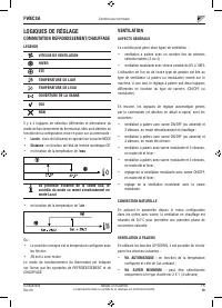
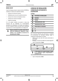
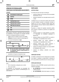
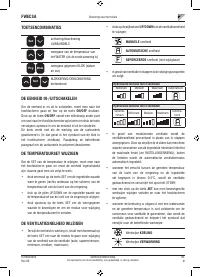
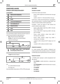
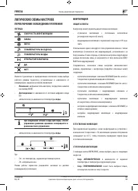
- 228 ЛОГИЧЕСКИЕ СХЕМЫ НАСТРОЕК; ПЕРЕКЛЮЧЕНИЕ ОХЛАЖДЕНИЯ/ОТОПЛЕНИЯ
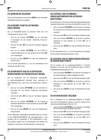
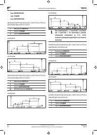
- 231 ФОРСИРОВКИ; КЛАПАН; МОДУЛИРУЮЩИЙ КЛАПАН
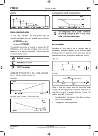
- 232 РАЗРЕШАЮЩИЙ СИГНАЛ ВОДНОЙ СИСТЕМЫ; ЭЛЕКТРИЧЕСКОЕ СОПРОТИВЛЕНИЕ; АКТИВИРОВАНИЕ; КОНТРОЛЬ МИНИМАЛЬНОЙ ТЕМПЕРАТУРЫ
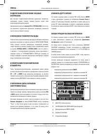
- 233 ОС УШЕНИЕ; ЛОГИЧЕСКАЯ СХЕМА; СИГНАЛЫ ТРЕВОГИ
- 234 СЕТИ И СВЯЗЬ; ПОДКЛЮЧЕНИЕ СИСТЕМЫ МОНИТОРИНГА; Протокол
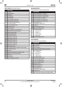
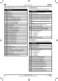
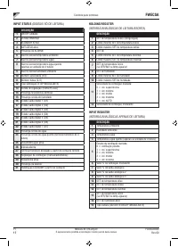
- 235 СТАТУС ВХОДА; РЕГИСТР ХРАНЕНИЯ; ВХОД РЕГИСТРА
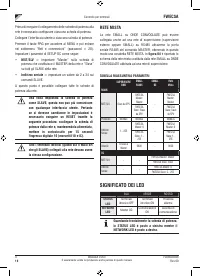
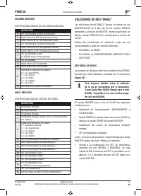
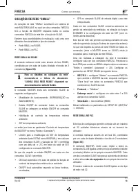
- 236 СЕТЕВОЙ ВАРИАНТ “SMALL”
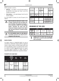
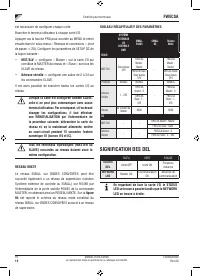
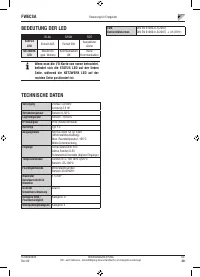
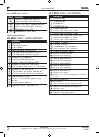
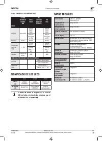
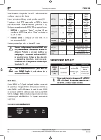
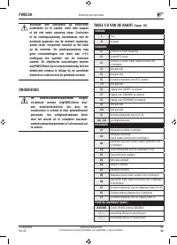
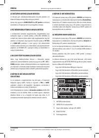
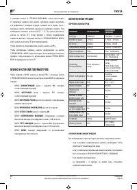
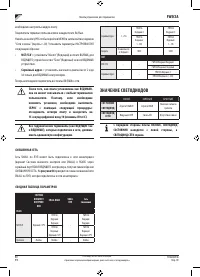
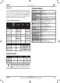
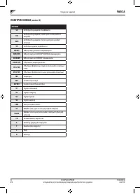
- 237 Серийный адрес; СМЕШЕННАЯ СЕТЬ; СВОДНАЯ ТАБЛИЦА ПАРАМЕТРОВ; ЗНАЧЕНИЕ СВЕТОДИОДОВ
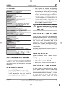
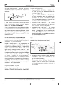
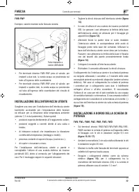
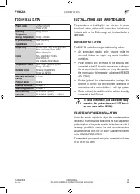
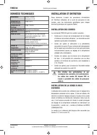
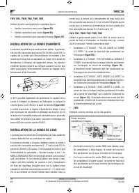
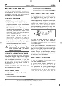
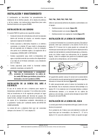
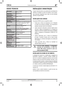
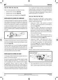
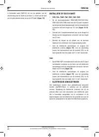
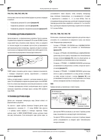
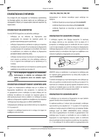
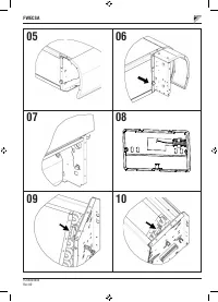
- 238 ТЕХНИЧЕСКИЕ ДАННЫЕ; УСТАНОВКА И ТЕХОБСЛУЖИВАНИЕ; УСТАНОВКА ЗОНДА; УСТАНОВКА УДАЛЕННОГО ДАТЧИКА ВОЗДУХА
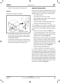
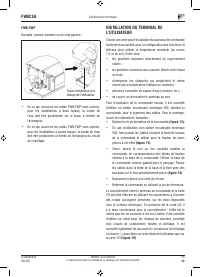
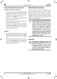
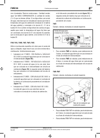
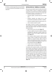
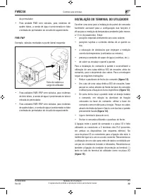
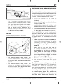
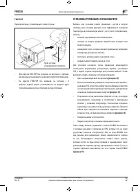
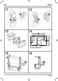
- 240 УСТАНОВКА ТЕРМИНАЛА ПОЛЬЗОВАТЕЛЯ
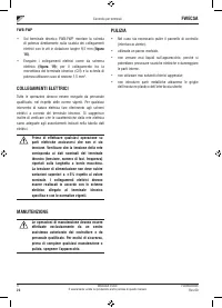
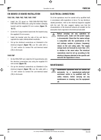
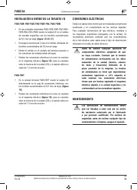
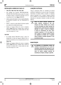
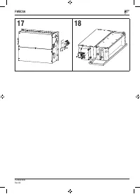
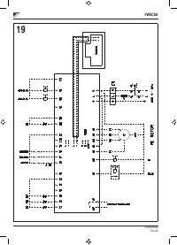
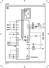
- 241 ПОДКЛЮЧЕНИЯ ЭЛЕКТРОСИСТЕМЫ
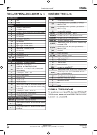
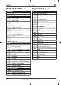
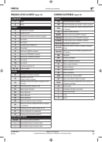
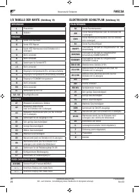
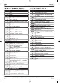
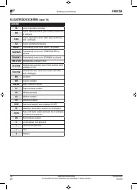
- 242 ЭЛЕКТРОСХЕМА


