
Пилы торцовочные Bosch 0.601.B23.100 - инструкция пользователя по применению, эксплуатации и установке на русском языке. Мы надеемся, она поможет вам решить возникшие у вас вопросы при эксплуатации техники.
Если остались вопросы, задайте их в комментариях после инструкции.
"Загружаем инструкцию", означает, что нужно подождать пока файл загрузится и можно будет его читать онлайн. Некоторые инструкции очень большие и время их появления зависит от вашей скорости интернета.


English |
41
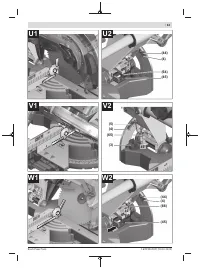
The leg of the angle gauge must be flush with the saw blade
(49)
along its entire length.
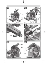
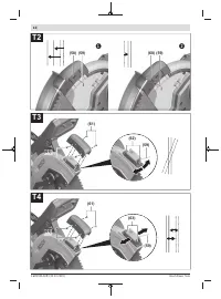
Setting (see figure W2)
– Loosen the lock nut of the stop screw
(66)
using a com-
mercially available box-ended or open-ended spanner
(size
10
mm).
– Turn the stop screw
(66)
as far in or out as needed until
the leg of the angle gauge is flush with the saw blade along
its entire length.
– Retighten the clamping lever
(8)
.
– Then retighten the lock nut of the stop screw
(66)
.
If the angle indicators
(44)
and
(5)
are not in line with the
45° marks on the scale
(4)
following adjustment, first check
the 0° setting for the bevel angle and the angle indicators
once more. Then repeat the adjustment of the 45° bevel
angle.
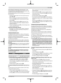
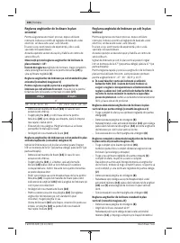
Aligning the scale for mitre angles
– Bring the power tool into the work position.
– Turn the saw table
(20)
to the 0° detent
(27)
. The lever
(24)
must be felt to engage in the detent.
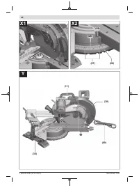
Checking (see figure X1)
– Set an angle gauge to 90° and position it between the
fence
(1)
and the saw blade
(49)
on the saw table
(20)
.
The leg of the angle gauge must be flush with the saw blade
(49)
along its entire length.
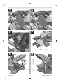
Setting (see figure X2)
– Loosen all four set screws
(67)
using the hex key (4 mm)
(39)
and turn the saw table
(20)
together with the scale
(28)
until the leg of the angle gauge is flush with the saw
blade along its entire length.
– Re-tighten the screws again.
If the angle indicator
(26)
is not aligned with the 0° mark on
the scale
(28)
following adjustment, loosen the screw
(68)
using a cross-headed screwdriver and align the angle indic-
ator along the 0° mark.
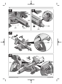
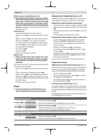
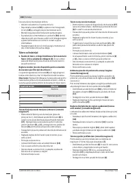
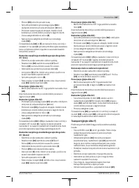
Transport (see figure Y)
Before transporting the power tool, the following steps must
be carried out:
– Loosen the locking screw
(6)
if it is tightened. Pull the
tool arm fully forwards and retighten the locking screw.
– Ensure that the depth stop
(42)
is swung all the way back
and the adjusting screw
(41)
fits through the recess
without touching the depth stop when you move the tool
arm.
– Push the saw table extensions all the way in and fix them
there.
– Bring the power tool into the transport position.
– Remove all accessories that cannot be securely fitted to
the power tool.
– If possible, transport unused saw blades in an enclosed
container.
– Tie the power cable and hook-and-loop strap
(69)
to-
gether.
– Carry the power tool by the transport handle
(11)
or
grasp the recessed handles
(30)
on the side of the saw
table
u
Only use the transport devices to transport the power
tool and never the protective devices.
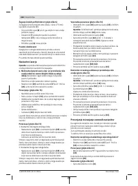
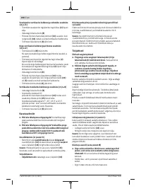
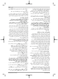
Maintenance and Service
Maintenance and cleaning
u
Pull the plug out of the socket before carrying out any
work on the power tool.
u
To ensure safe and efficient operation, always keep
the power tool and the ventilation slots clean.
In order to avoid safety hazards, if the power supply cord
needs to be replaced, this must be done by
Bosch
or by an
after-sales service centre that is authorised to repair
Bosch
power tools.
The retracting blade guard must always be able to move
freely and retract automatically. It is therefore important to
keep the area around the retracting blade guard clean at all
times.
Always remove dust and chips after working by blowing out
with compressed air or using a brush.
Clean the guide roller
(17)
regularly.
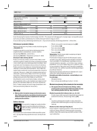
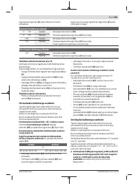
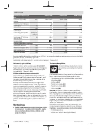
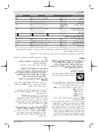
Noise reduction measures
Measures implemented by the manufacturer:
– Soft start
– Provided with a saw blade specially developed for noise
reduction
Measures implemented by the operator:
– Low-vibration mounting on a stable work surface
– Use of saw blades with noise-reducing functions
– Regular cleaning of the saw blade and power tool
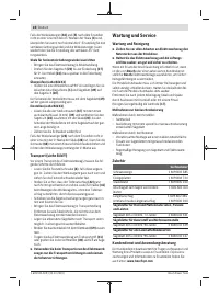
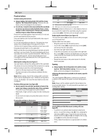
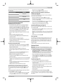
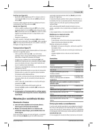
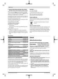
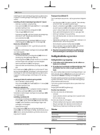
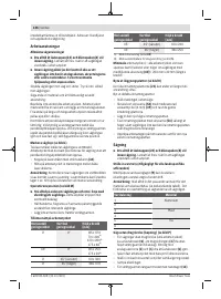
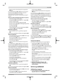
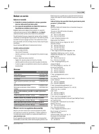
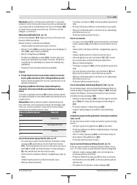
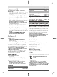
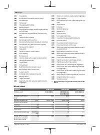
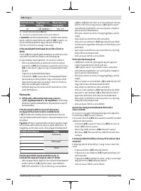
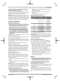
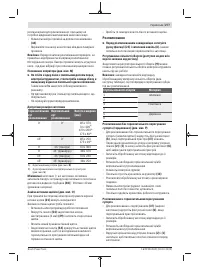
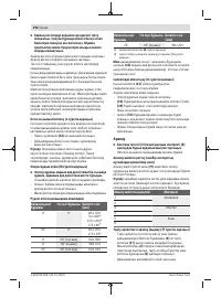
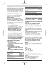
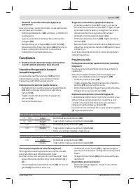
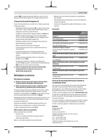
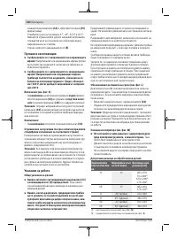
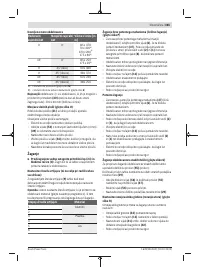
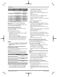
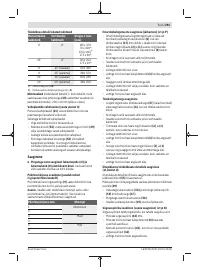
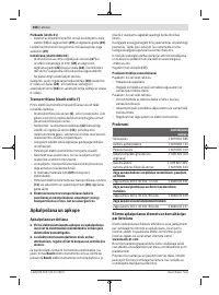
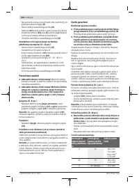
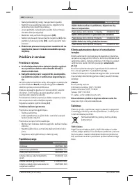
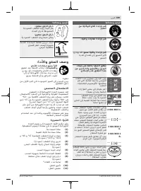
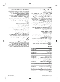
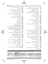
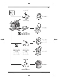
Accessories
Article number
Screw clamp
1 609 B02 585
Insert plates
1 609 B04 724
Dust bag
1 609 B05 010
Stop kit for sawing ceiling strips
1 600 A01 4LX
Length stop
Locking screw for length stop
1 609 B02 365
1 609 B00 263
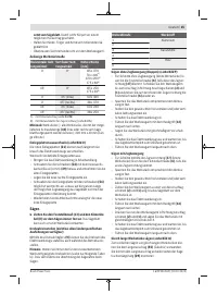
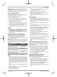
Saw blades for wood and fibreboard, panels and strips
305 x 30 mm saw blade, 72 teeth
2 608 642 531
Saw blades for plastic and non-ferrous metals
305 x 30 mm saw blade, 96 teeth
2 608 642 529
Saw blades for all types of laminate flooring
305 x 30 mm saw blade, 96 teeth
2 608 642 137
Bosch Power Tools
1 609 92A 5U9 | (20.10.2020)
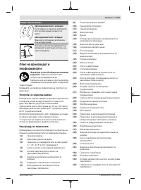
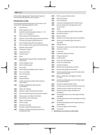
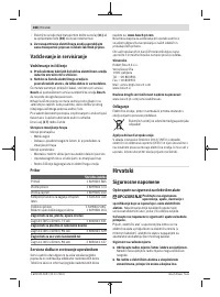
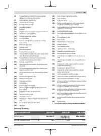
Содержание
- 253 Содержите рабочее место в чистоте.
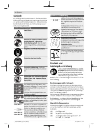
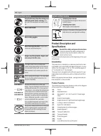
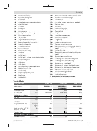
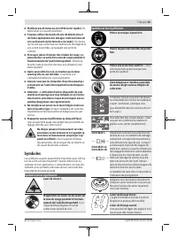
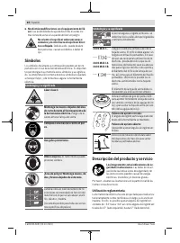
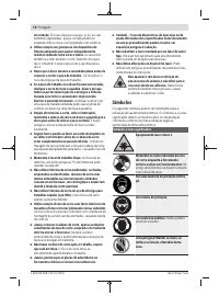
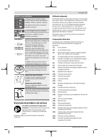
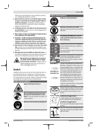
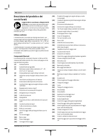
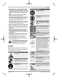
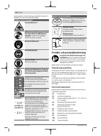
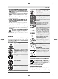
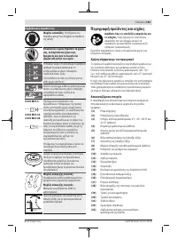
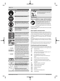
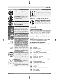
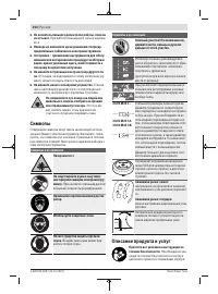
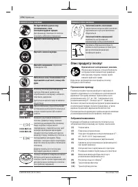
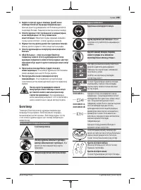
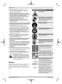
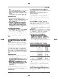
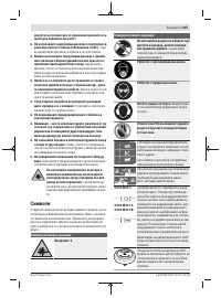
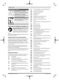
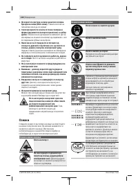
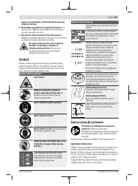
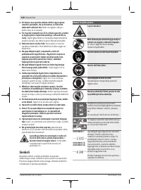
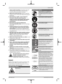
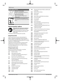
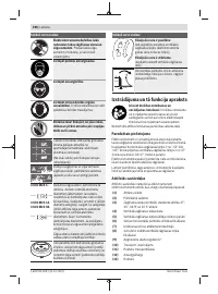
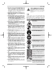
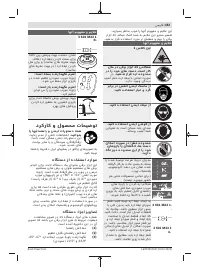
- 254 Не меняйте ничего в лазерном устройстве.; Символы; Символы и их значение; Описание продукта и услуг
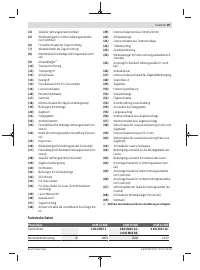
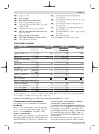
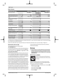
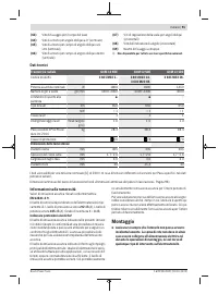
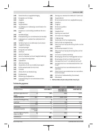
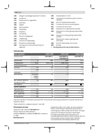
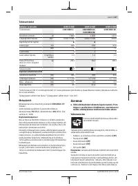
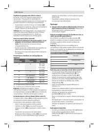
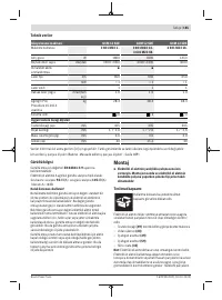
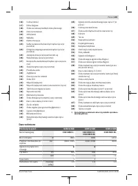
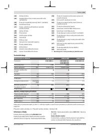
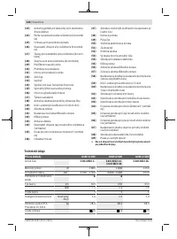
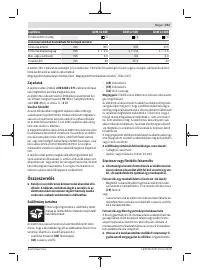
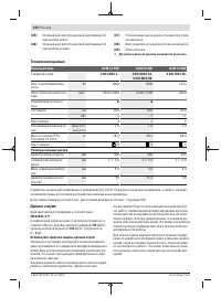
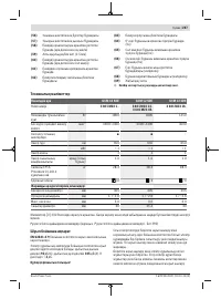
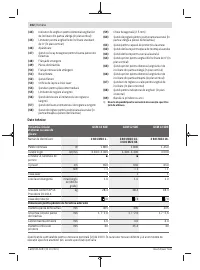
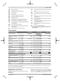
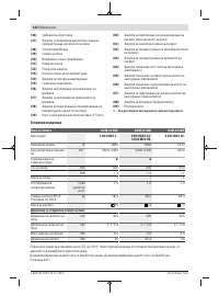
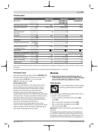
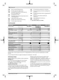
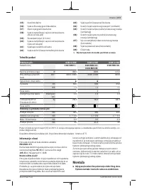
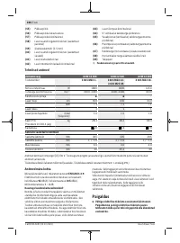
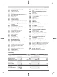
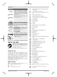
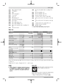
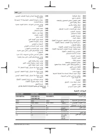
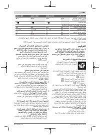
- 256 Технические данные; Панельная пила; Данные о шуме; Используйте средства защиты органов слуха!
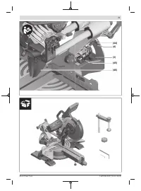
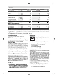
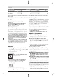
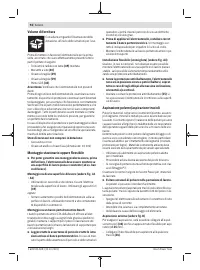
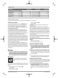
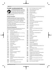
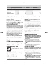
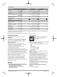
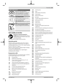
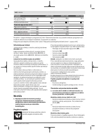
- 257 Сборка; Комплект поставки; Монтаж на верстаке производства Bosch; Удаление пыли и стружки; Избегайте скопления пыли на рабочем месте.
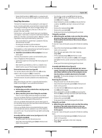
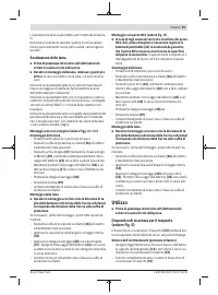
- 258 Замена пильного диска; Монтаж пильного диска; Работа с инструментом
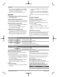
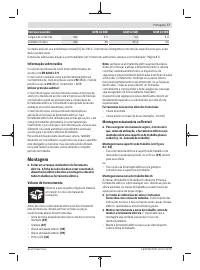
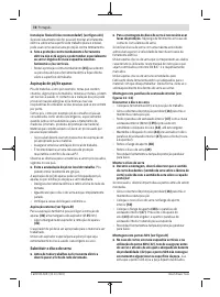
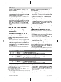
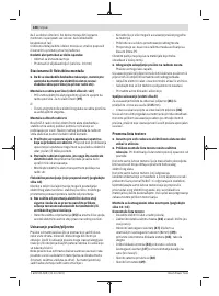
- 259 Подготовка эксплуатации; Вертикальный диапазон угла распила; Настройка горизонтального угла распила; слева
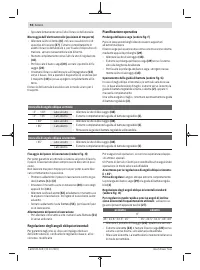
- 260 Настройка вертикального угла распила; Включение электроинструмента
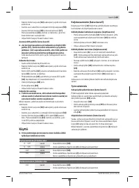
- 261 Указания по применению; Общие указания для пиления; Пиление
- 262 Юстирование лазера
- 263 Основные настройки – контроль и коррекция
- 265 Техобслуживание и сервис; Техобслуживание и очистка; Принадлежности; Товарный номер
- 266 Россия; Утилизация; Українська; Вказівки з техніки безпеки; Загальні застереження для електроприладів; ДЖЕННЯ; електроінструментом.
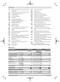
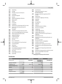
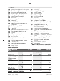
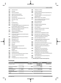
Характеристики

Остались вопросы?Не нашли свой ответ в руководстве или возникли другие проблемы? Задайте свой вопрос в форме ниже с подробным описанием вашей ситуации, чтобы другие люди и специалисты смогли дать на него ответ. Если вы знаете как решить проблему другого человека, пожалуйста, подскажите ему :)


