
Пилы торцовочные Bosch 0.601.B23.100 - инструкция пользователя по применению, эксплуатации и установке на русском языке. Мы надеемся, она поможет вам решить возникшие у вас вопросы при эксплуатации техники.
Если остались вопросы, задайте их в комментариях после инструкции.
"Загружаем инструкцию", означает, что нужно подождать пока файл загрузится и можно будет его читать онлайн. Некоторые инструкции очень большие и время их появления зависит от вашей скорости интернета.


36
| English
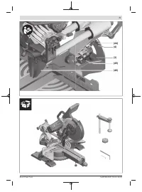
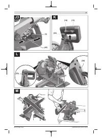
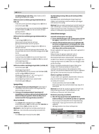
– Attach the clamping flange
(48)
and the SDS bolt
(32)
.
Press the spindle lock
(43)
until it engages and tighten
the SDS bolt by turning it anticlockwise.
– Slowly push the retracting blade guard back down.
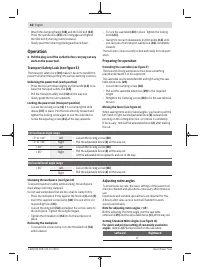
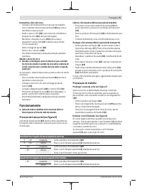
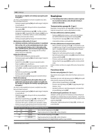
Operation
u
Pull the plug out of the socket before carrying out any
work on the power tool.
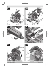
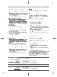
Transport Safety Lock (see figure E)
The transport safety lock
(10)
makes it easier to handle the
power tool when transporting it to various working locations.
Unlocking the power tool (work position)
– Press the tool arm down slightly by the handle
(13)
to re-
lease the transport safety lock
(10)
.
– Pull the transport safety lock
(10)
all the way out.
– Slowly guide the tool arm upwards.
Locking the power tool (transport position)
– Loosen the locking screw
(6)
if it is clamping the slide
device
(37)
in place. Pull the tool arm fully forward and
tighten the locking screw again to lock the slide device.
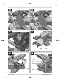
– Screw the adjusting screw
(41)
all the way upwards.
– To lock the saw table
(20)
in place, tighten the locking
knob
(23)
.
– Swing the tool arm downwards by the handle
(13)
until
you can press the transport safety lock
(10)
completely
inwards.
The tool arm is now securely locked and ready for transport-
ation.
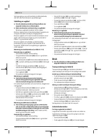
Preparing for operation
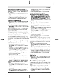
Extending the saw table (see figure F)
The free end of long workpieces must have something
placed underneath it or be supported.
The saw table can be extended left and right using the saw
table extensions
(29)
.
– Loosen the clamping screw
(18)
.
– Pull out the saw table extension
(29)
to the required
length.
– Retighten the clamping screw
(18)
to fix the saw table ex-
tension.
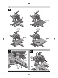
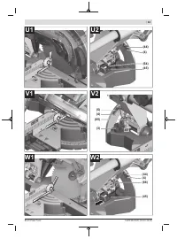
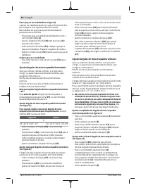
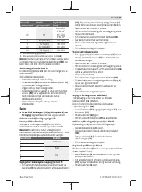
Moving the fence (see figure G)
When sawing mitre and/or bevel angles, you have to pull the
left-hand or right-hand adjustable fence
(2)
outwards de-
pending on the cutting direction, or remove it completely.
If necessary, reinstall the adjustable fence
(2)
after making
the cut.
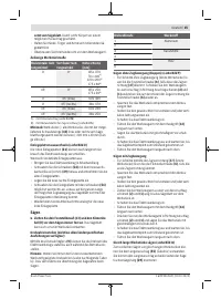
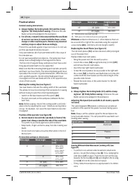
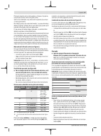
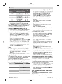
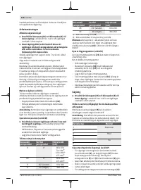
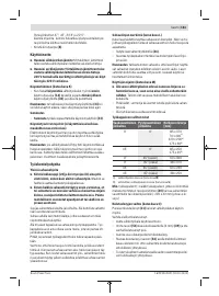
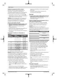
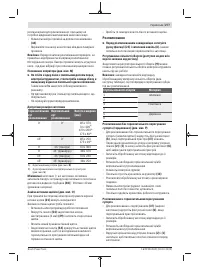
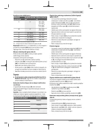
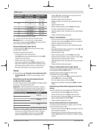
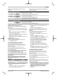
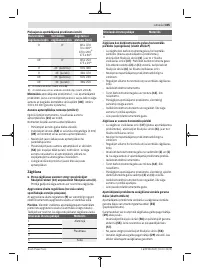
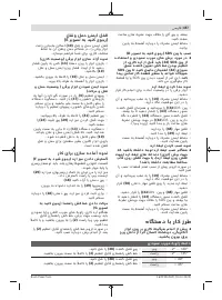
Vertical bevel angle range
–2° to +40°
Left
– Loosen the locking screw
(38)
.
– Pull the adjustable fence
(2)
all the way out.
–2° to +35°
Right
> 40°
Left
– Loosen the locking screw
(38)
.
– Pull the adjustable fence
(2)
all the way out.
– Lift the adjustable fence upwards and out of the way.
> 35°
Right
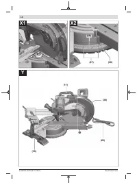
Horizontal bevel angle range
> 45°
Left
– Loosen the locking screw
(38)
.
– Pull the adjustable fence
(2)
all the way out.
Right
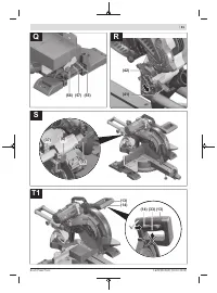
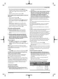
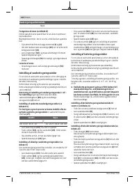
Clamping the workpiece (see figure H)
To ensure maximum safety while working, the workpiece
must always be firmly clamped.
Do not saw workpieces that are too small to clamp firmly.
– Press the workpiece firmly against the fences
(1)
and
(2)
.
– Insert the supplied screw clamp
(40)
into one of the cor-
responding holes
(31)
.
– Loosen the wing bolt
(52)
and adjust the screw clamp to
the workpiece. Tighten the wing bolt again.
– Tighten the threaded rod
(51)
to fix the workpiece in
place.
Releasing the workpiece
– To loosen the screw clamp, turn the threaded rod
(51)
anticlockwise.
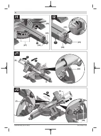
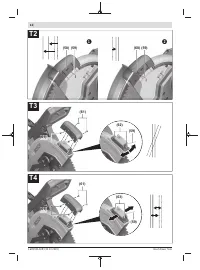
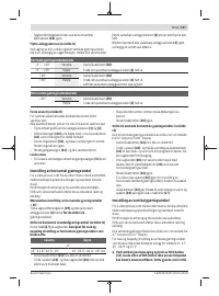
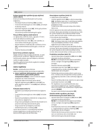
Adjusting mitre angles
To ensure precise cuts, the basic settings of the power tool
must be checked and adjusted as necessary after intensive
use.
Experience and suitable special tools are required for this.
A Bosch after-sales service point will handle this work
quickly and reliably.
Note for adjusting mitre angles > 45°:
Before adjusting the mitre angle, pull the saw table
extension
(29)
and the adjustable fence
(2)
all the way out.
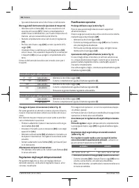
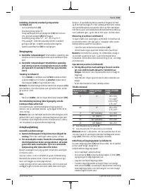
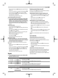
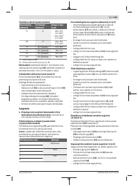
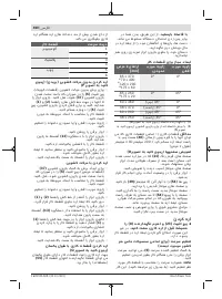
Setting Standard Mitre Angles (see figure I1)
For quick and precise setting of commonly used mitre
angles
, detents
(27)
are provided on the saw table:
Leftward
Rightward
0°
1 609 92A 5U9 | (20.10.2020)
Bosch Power Tools
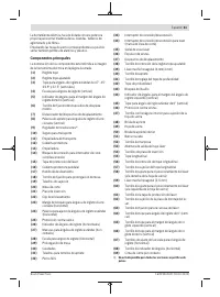
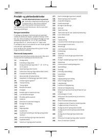
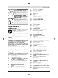
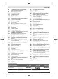
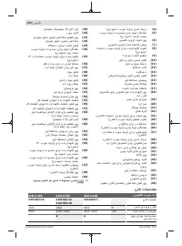
Содержание
- 253 Содержите рабочее место в чистоте.
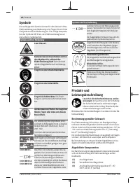
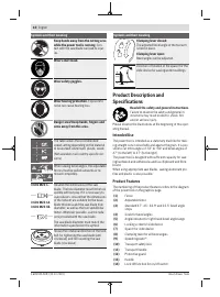
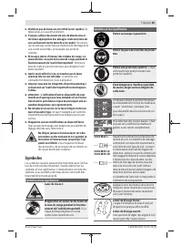
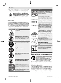
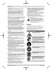
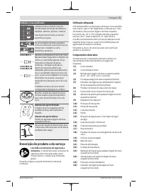
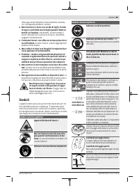
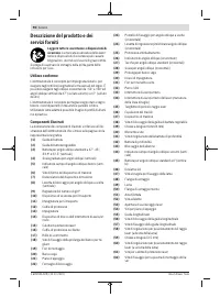
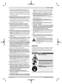
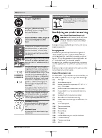
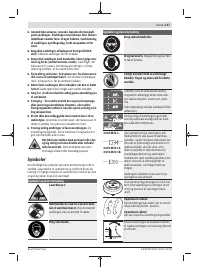
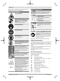
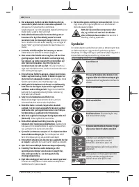
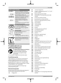
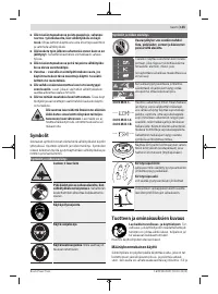
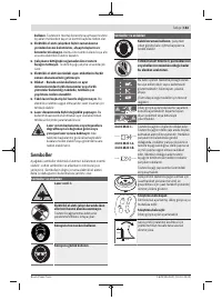
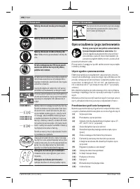
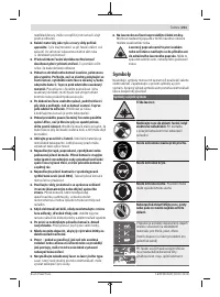
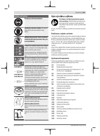
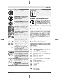
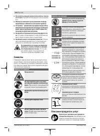
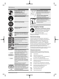
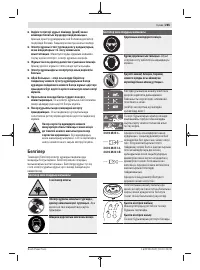
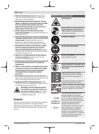
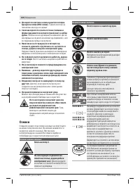
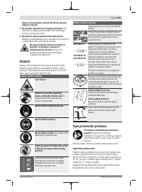
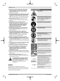
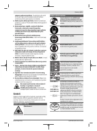
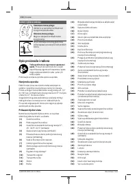
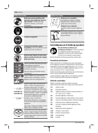
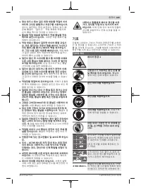
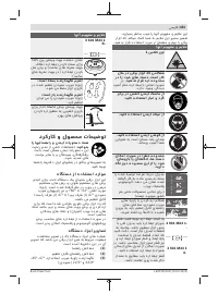
- 254 Не меняйте ничего в лазерном устройстве.; Символы; Символы и их значение; Описание продукта и услуг
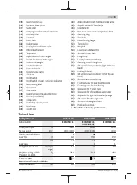
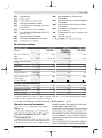
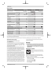
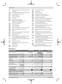
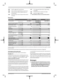
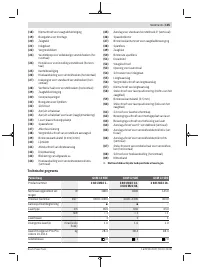
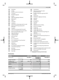
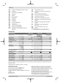
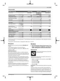
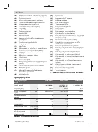
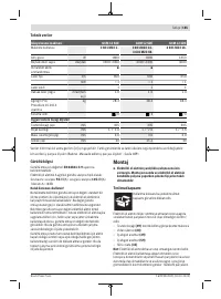
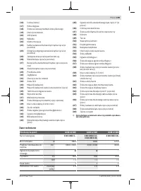
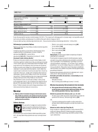
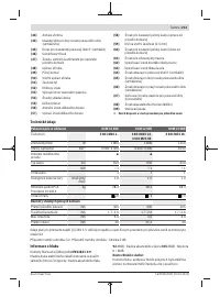
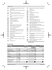
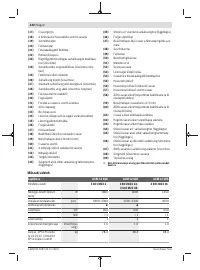
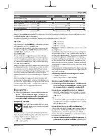
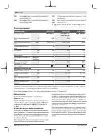
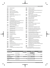
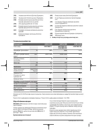
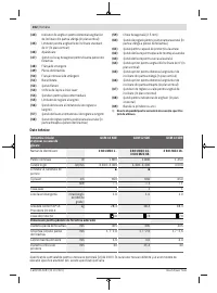
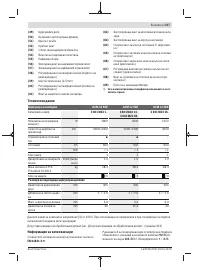
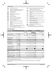
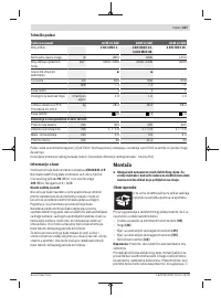
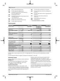
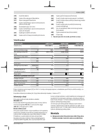
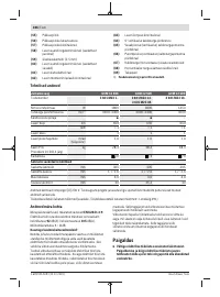
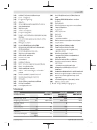
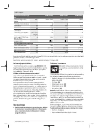
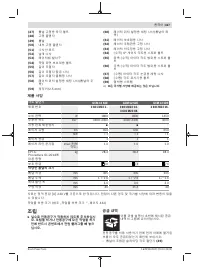
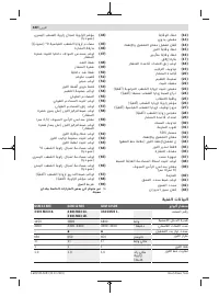
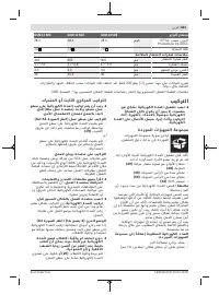
- 256 Технические данные; Панельная пила; Данные о шуме; Используйте средства защиты органов слуха!
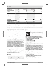
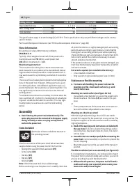
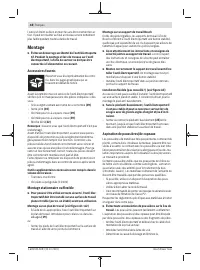
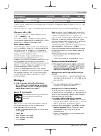
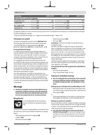
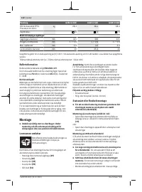
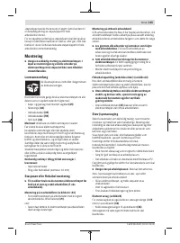
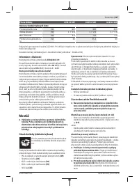
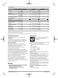
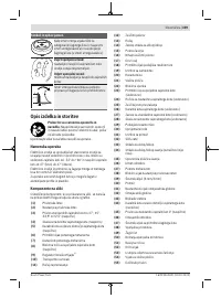
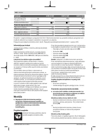
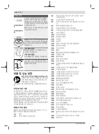
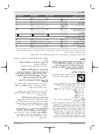
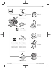
- 257 Сборка; Комплект поставки; Монтаж на верстаке производства Bosch; Удаление пыли и стружки; Избегайте скопления пыли на рабочем месте.
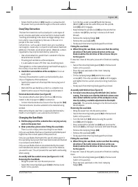
- 258 Замена пильного диска; Монтаж пильного диска; Работа с инструментом
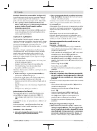
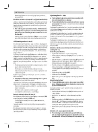
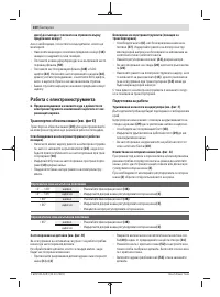
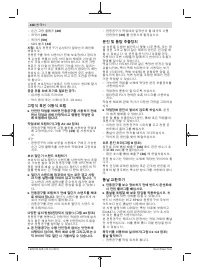
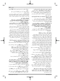
- 259 Подготовка эксплуатации; Вертикальный диапазон угла распила; Настройка горизонтального угла распила; слева
- 260 Настройка вертикального угла распила; Включение электроинструмента
- 261 Указания по применению; Общие указания для пиления; Пиление
- 262 Юстирование лазера
- 263 Основные настройки – контроль и коррекция
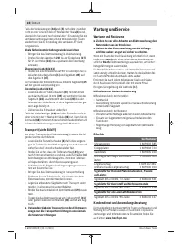
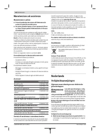
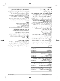
- 265 Техобслуживание и сервис; Техобслуживание и очистка; Принадлежности; Товарный номер
- 266 Россия; Утилизация; Українська; Вказівки з техніки безпеки; Загальні застереження для електроприладів; ДЖЕННЯ; електроінструментом.
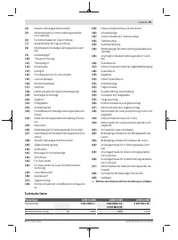
Характеристики

Остались вопросы?Не нашли свой ответ в руководстве или возникли другие проблемы? Задайте свой вопрос в форме ниже с подробным описанием вашей ситуации, чтобы другие люди и специалисты смогли дать на него ответ. Если вы знаете как решить проблему другого человека, пожалуйста, подскажите ему :)


