Пилы дисковые Bosch GTS 10 J - инструкция пользователя по применению, эксплуатации и установке на русском языке. Мы надеемся, она поможет вам решить возникшие у вас вопросы при эксплуатации техники.
Если остались вопросы, задайте их в комментариях после инструкции.
"Загружаем инструкцию", означает, что нужно подождать пока файл загрузится и можно будет его читать онлайн. Некоторые инструкции очень большие и время их появления зависит от вашей скорости интернета.


36
| English
1 609 92A 15R | (26.1.15)
Bosch Power Tools
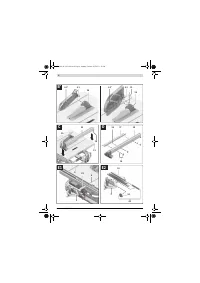
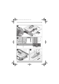
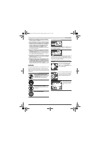
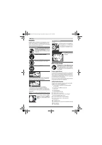
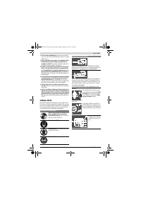
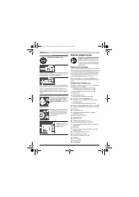
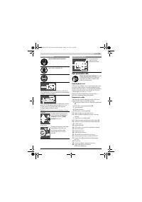
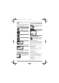
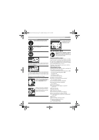
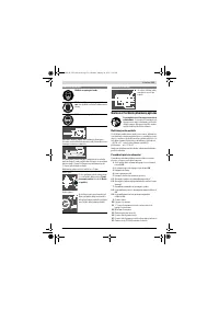
Adjusting the Parallelism of the Parallel Guide
(see figure W)
– Bring the power tool into the working position.
– Tilt the blade guard
6.x
toward the rear to the stop.
– Loosen the clamping handle
35
of the parallel guide and
slide it until it touches the saw blade.
Checking:
The parallel guide
10
must touch the saw blade over the com-
plete length.
Adjusting:
– Loosen the hex socket screws
71
using the supplied hex
key
21
.
– Carefully move the parallel guide
10
until it touches the
saw blade over the complete length.
– Hold the parallel guide in this position and press the clamp-
ing handle
35
down again.
– Retighten the hex socket screws
71
.
Adjusting the Tension Force of the Parallel Guide
The tensioning force of the parallel guide
10
can decrease af-
ter frequent usage.
– Tighten the adjustment screw
70
until the parallel guide
can be firmly affixed on the saw table again.
Adjusting the Lens of the Parallel Guide (see figure W)
– Bring the power tool into the working position.
– Tilt the blade guard
6.x
toward the rear to the stop.
– Move parallel guide
10
from the right until it touches the
saw blade.
Checking:
The mark of lens
27
must be in a line with the 0 ° mark of scale
1
.
Adjusting:
– Loosen screw
62
using a cross-head screwdriver and align
the clearance indicator alongside the 0 ° mark.
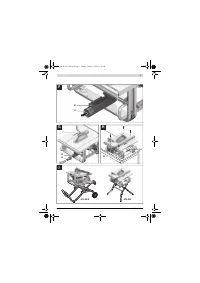
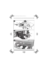
Adjusting the Level of the Insert Plate (see figure X)
Checking:
The front side of the insert plate
24
must be flush with or
somewhat lower than the saw table; the rear side must be
flush with or somewhat above the saw table.
Adjusting:
– Remove the insert plate
24
.
– Adjust the correct level of the four adjusting screws
63
with the hex key
64
.
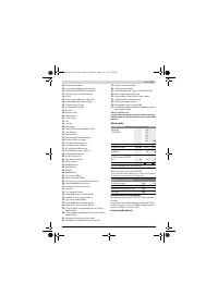
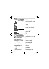
Storage and Transport
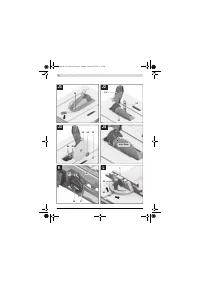
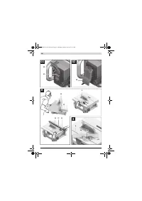
Storing Product Features (see figures Y1 – Y6)
For storage purposes, certain product features can be se-
curely fastened to the power tool.
– Loosen auxiliary parallel guide
37
from parallel guide
10
.
– Attach all loose tool parts to their storage locations on the
housing. (see Table)
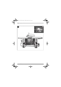
Carrying the Power Tool
Before transporting the power tool, the following steps must
be carried out:
– Bring the machine into the transport position
(see “Transport Position”, page 33).
– Remove all accessories that cannot be mounted firmly to
the power tool.
If possible, place unused saw blades in an enclosed con-
tainer for transport.
– Slide the saw-table extension
14
completely inward and
press tensioning lever
15
downward to lock it.
– Wind the mains cable around the cable holder
29
.
– For lifting or transport, use the recessed handles
4
or the
carrying handle
13
.
When transporting the power tool, use only the trans-
port devices and never use the protective devices.
The power tool should always be carried by two per-
sons in order to avoid back injuries.
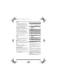
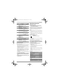
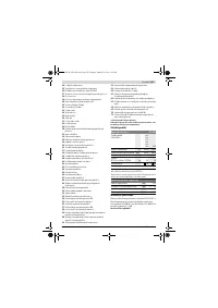
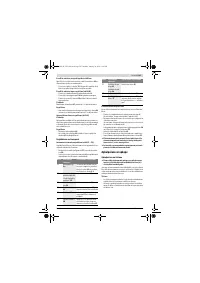
Figure Product Feature Storage Location
Y1
Blade guard
6.x
Insert into the recess of fixture
33
and tighten with clamping
lever
8.1
or clamping screw
8.2
Y2
“Auxiliary parallel
guide” fastening
kit
38
Clip into the holders
65
Y2
Extraction adapter
32
Insert into retaining clamp
66
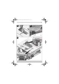
Y3
Ring spanner
22
Fasten in tool depot with fas-
tening nut
67
Y3
Push stick
23
Mount onto fastening nut
67
and fasten by turning
Y4
Parallel guide
10
Turn guide around and hang it
into the guide rails from below;
tighten clamping handle
35
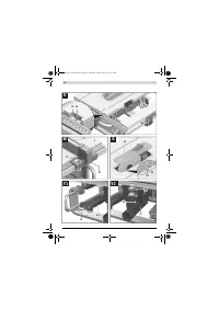
Y5
Hex key
21
Hex key
64
Insert into holders
68
Y5
Angle stop
3
Insert into retaining clamp
69
Y6
Auxiliary parallel
guide
37
Insert into retaining brackets
30
(short side goes on top; long
side toward the rear)
OBJ_BUCH-1325-003.book Page 36 Monday, January 26, 2015 1:18 PM
Содержание
- 218 или подвижных частей электроинструмента.
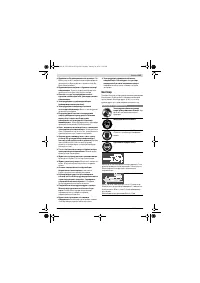
- 219 Всегда распиливайте только одну деталь.; Символы; Символы и их значение
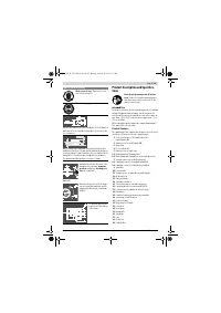
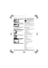
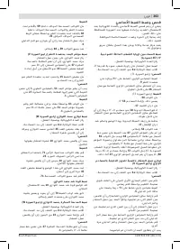
- 220 Описание продукта и услуг; Применение по назначению; Используйте защитные очки.
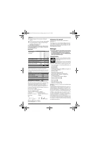
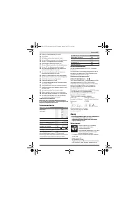
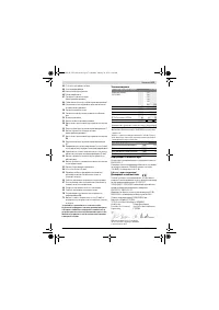
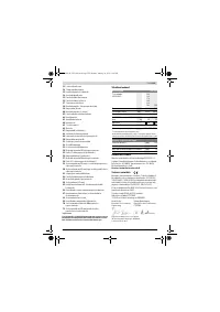
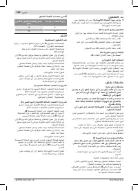
- 221 Технические данные; Настольная дисковая пила; Размеры пильных дисков
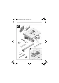
- 222 Данные о шуме; Применяйте средства защиты органов слуха!; Сборка; Комплект поставки
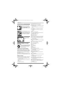
- 223 Отсос пыли и стружки; Избегайте скопления пыли на рабочем месте.; Стационарный или временный монтаж
- 224 Демонтаж пильного диска; Работа с инструментом; Транспортное положение; Настройка угла распила
- 225 Установка параллельного упора; при не вытянутом столе; Регулировка распорного клина; Примите во внимание напряжение в сети!
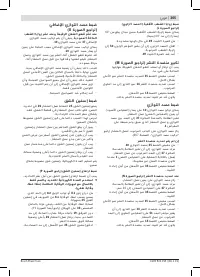
- 226 Отказ электропитания; Указания по применению; Общие указания для пиления; Пиление; Выполнение прямых пропилов; Основные настройки – контроль и коррекция; Вертикальный угол
- 227 Настройка усилия зажатия параллельного упора
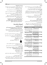
- 228 Хранение и транспортировка; Перенос электроинструмента; Техобслуживание и сервис; Техобслуживание и очистка; Очистка
- 229 Меры по уменьшению уровня шума; Принадлежности; Россия; Утилизация; Товарный No
Характеристики

Остались вопросы?Не нашли свой ответ в руководстве или возникли другие проблемы? Задайте свой вопрос в форме ниже с подробным описанием вашей ситуации, чтобы другие люди и специалисты смогли дать на него ответ. Если вы знаете как решить проблему другого человека, пожалуйста, подскажите ему :)


