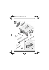
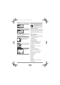
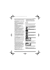
Пилы дисковые Bosch GTS 10 J - инструкция пользователя по применению, эксплуатации и установке на русском языке. Мы надеемся, она поможет вам решить возникшие у вас вопросы при эксплуатации техники.
Если остались вопросы, задайте их в комментариях после инструкции.
"Загружаем инструкцию", означает, что нужно подождать пока файл загрузится и можно будет его читать онлайн. Некоторые инструкции очень большие и время их появления зависит от вашей скорости интернета.


English |
33
Bosch Power Tools
1 609 92A 15R | (26.1.15)
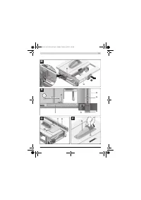
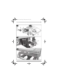
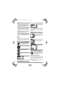
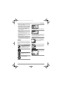
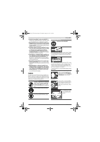
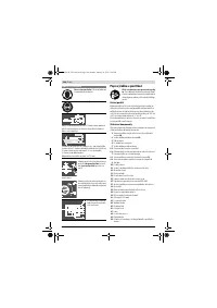
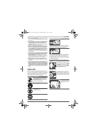
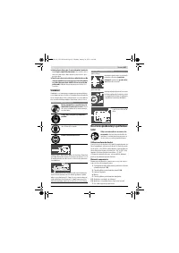
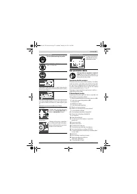
When mounting the saw blade, pay attention that the
cutting direction of the teeth (arrow direction on the
saw blade) corresponds with the direction of the arrow
on the blade guard!
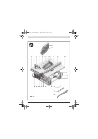
– Mount the clamping flange
44
and the clamping nut
42
.
– Turn the clamping nut
42
with the ring spanner
22
(23 mm) and at the same time, pull the spindle lock lever
43
until it engages.
– Tighten the clamping nut in clockwise direction
(Tightening torque approx. 15 – 23 Nm).
– Reinsert the insert plate
24
.
– Tilt blade guard
6.x
down again.
Operation
Before any work on the machine itself, pull the mains
plug.
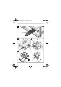
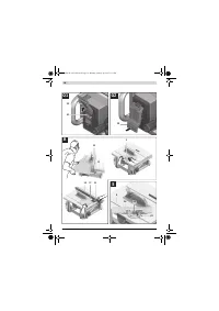
Transport and Working Position of the Saw Blade
Transport Position
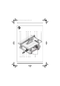
– Turn the handwheel
18
in anticlockwise direction until the
teeth of the saw blade
26
are positioned below the saw ta-
ble
9
.
– Slide the table extension
14
completely inward.
Press tensioning lever
15
downward.
The saw-table extension is now locked.
For additional information on transport, see page 36.
Working Position
– Turn the crank
19
clockwise, until the teeth of the saw
blade
26
are positioned above the workpiece.
Note:
Take care that the blade guard is properly positioned.
When sawing, it must always face against the workpiece.
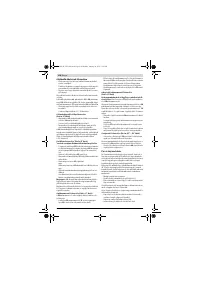
Adjusting the Cutting Angle
To ensure precise cuts, the basic adjustment of the machine
must be checked and adjusted as necessary after intensive
use (see “Checking and Adjusting the Basic Adjustment”,
page 35).
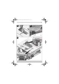
Adjusting Bevel Angles (Saw Blade)
(see figure K)
The bevel angle can be set in the range from –2 ° to 47 °.
– Turn locking lever
17
in anticlockwise direction.
Note:
By completely loosening the locking knob, the saw
blade tilts approx. to the 30 ° position by means of gravity
force.
– Push or pull handwheel
18
alongside the connecting link
until the angle indicator
47
indicates the desired bevel an-
gle.
– Hold the handwheel in this position and tighten locking le-
ver
17
again.
For quick and precise setting of the standard 0 ° and 45 °
angles, factory-set stops have been provided for.
Adjusting Mitre Angles (Angle Stop)
(see figure L)
The mitre angle can be set in the range from 60 ° (left side) to
60 ° (right side).
– Loosen the locking knob
49
in case it is tightened.
– Turn the angle stop until the angle indicator
50
indicates
the requested mitre angle.
– Tighten the locking knob
49
again.
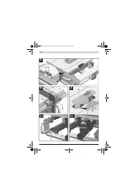
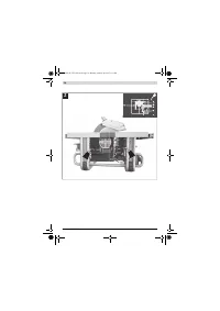
Increasing the Size of the Saw Table
(see figure M)
Long workpieces must be underlaid or supported at their free
end.
– Completely pull tensioning lever
15
of the saw-table exten-
sion upward.
– Pull out the saw-table extension
14
to the desired length.
– Press tensioning lever
15
downward.
The saw-table extension is now locked.
Adjusting the Parallel Guide
The parallel guide
10
can be positioned either left (black
scale) or right (silver scale) from the saw blade.
The mark in the lens
27
indicates the set clearance of the par-
allel guide to the saw blade on the scale
1
.
Position the parallel guide on the desired side of the saw
blade (see “Mounting the Parallel Guide”, page 31).
With the Saw Table not Extended
– Loosen clamping handle
35
of parallel guide
10
.
Move the parallel guide until the mark in the lens
27
indi-
cates the desired clearance to the saw blade.
When the saw table is not extended, the bottom labelling of
the silver scale applies
1
.
– To lock the parallel guide, press clamping handle
35
down
again.
With the Saw Table Extended (see figure N)
– Position the parallel guide on the right side of the saw
blade.
Move the parallel guide until the mark in the lens
27
indi-
cates 26 cm on the bottom scale.
To lock the parallel guide, press clamping handle
35
down
again.
– Completely pull tensioning lever
15
of the saw-table exten-
sion upward.
– Pull saw-table extension
14
outward until clearance indi-
cator
51
indicates the desired clearance to the saw blade
on the top scale.
– Press tensioning lever
15
downward.
The saw-table extension is now locked.
OBJ_BUCH-1325-003.book Page 33 Monday, January 26, 2015 1:18 PM
Содержание
- 218 или подвижных частей электроинструмента.
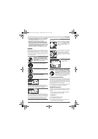
- 219 Всегда распиливайте только одну деталь.; Символы; Символы и их значение
- 220 Описание продукта и услуг; Применение по назначению; Используйте защитные очки.
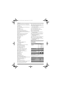
- 221 Технические данные; Настольная дисковая пила; Размеры пильных дисков
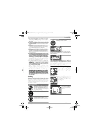
- 222 Данные о шуме; Применяйте средства защиты органов слуха!; Сборка; Комплект поставки
- 223 Отсос пыли и стружки; Избегайте скопления пыли на рабочем месте.; Стационарный или временный монтаж
- 224 Демонтаж пильного диска; Работа с инструментом; Транспортное положение; Настройка угла распила
- 225 Установка параллельного упора; при не вытянутом столе; Регулировка распорного клина; Примите во внимание напряжение в сети!
- 226 Отказ электропитания; Указания по применению; Общие указания для пиления; Пиление; Выполнение прямых пропилов; Основные настройки – контроль и коррекция; Вертикальный угол
- 227 Настройка усилия зажатия параллельного упора
- 228 Хранение и транспортировка; Перенос электроинструмента; Техобслуживание и сервис; Техобслуживание и очистка; Очистка
- 229 Меры по уменьшению уровня шума; Принадлежности; Россия; Утилизация; Товарный No
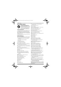
Характеристики

Остались вопросы?Не нашли свой ответ в руководстве или возникли другие проблемы? Задайте свой вопрос в форме ниже с подробным описанием вашей ситуации, чтобы другие люди и специалисты смогли дать на него ответ. Если вы знаете как решить проблему другого человека, пожалуйста, подскажите ему :)


