Сварочное оборудование Telwin TECHNOLOGY TIG 185 DC HF LIFT - инструкция пользователя по применению, эксплуатации и установке на русском языке. Мы надеемся, она поможет вам решить возникшие у вас вопросы при эксплуатации техники.
Если остались вопросы, задайте их в комментариях после инструкции.
"Загружаем инструкцию", означает, что нужно подождать пока файл загрузится и можно будет его читать онлайн. Некоторые инструкции очень большие и время их появления зависит от вашей скорости интернета.

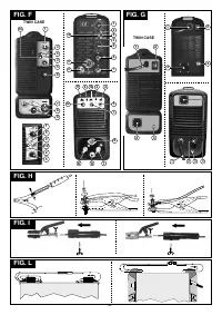
torch gas pipe to the appropriate connector (if present).
SLOPE DOWN function (if it has been set) to reach the minimum welding current The
Connecting the electrode-holder clamp welding cable
minimum current will be maintained until the button is released to terminate the
- On the end take a special terminal that is used to close the uncovered part of the
welding cycle and start the post gas phase.
electrode.
If, on the other hand, you release the button while the SLOPE DOWN function is
This cable is connected to the terminal with the symbol (+)
proceeding, the welding cycle will terminate immediately and the post gas phase will
Connection to the gas bottle
start (
FIG.Q
).
- Screw the pressure reducing valve to the gas bottle valve, if necessary inserting the
special reduction adapter supplied as an accessory.
6.2 MMA WELDING
- Connect the gas inlet pipe to the pressure-reducing valve and tighten the band
6.2.1 Comments
supplied.
- It is most important that the user refers to the maker's instructions indicated on the
- Loosen the adjustment ring nut on the pressure-reducing valve before opening the
stick electrode packaging. This will indicate the correct polarity of the stick
bottle valve.
electrode and the most suitable current.
- Open the valve on the bottle and adjust the quantity of gas (l/min) according to the
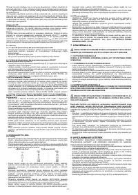
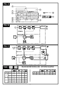
- The welding current must be regulated according to the diameter of the electrode in
suggestions for use given in the table
(TAB. 3)
; if it is necessary to adjust the gas flow
use and the type of the joint to be carried out: see below the currents corresponding
during welding this should always be done by adjusting the ring nut on the pressure
to various electrode diameters:
reduction valve. Make sure there are no leaks in the piping and connectors.
ø Electrode (mm)
Welding current (A)
WARNING! Always close the gas bottle valve at the end of the job.
min.
max.
1.6
25
-
50
5.5.2 MMA WELDING
2
40
-
80
Almost all coated electrodes are connected to the positive pole (+) of the power source;
2.5
60
-
110
as an exception to the negative pole (-) for acid coated electrodes.
3.2
80
-
160
Connecting the electrode-holder clamp welding cable
4
120
-
200
On the end take a special terminal that is used to close the uncovered part of the
5
150
-
280
electrode.
- The user must consider that, according to the electrode diameter, higher current
This cable is connected to the terminal with the symbol (+)
values must be used for flat welding, whereas for vertical or overhead welds lower
current values are necessary.
Connecting the welding current return cable
- As well as being determined by the chosen current intensity, the mechanical
This is connected to the piece being welded or to the metal bench supporting it, as close
characteristics of the welded join are also determined by the other welding
as possible to the join being made.
parameters i.e. arc length, working rate and position, electrode diameter and quality
This cable is connected to the terminal with the symbol (-)
(to store the electrodes correctly, keep them in a dry place protected by their
packaging or containers).
6. WELDING: DESCRIPTION OF THE PROCEDURE
- The properties of the weld also depend on the ARC-FORCE value (dynamic
6.1.1 General principles
behaviour) of the welding machine. The setting for this parameter can be made (when
TIG welding is a welding procedure that exploits the heat produced by the electric arc
available) at the control panel, or else using the remote control with 2 potentiometers.
that is struck, and maintained, between a non-consumable electrode (tungsten) and the
- It should be noted that high ARC-FORCE values achieve better penetration and allow
piece to be welded. The tungsten electrode is supported by a torch suitable for
welding in any position typically with basic electrodes, low ARC-FORCE values give a
transmitting the welding current to it and protecting the electrode itself and the weld pool
softer, spray-free arc typically with rutile electrodes.
from atmospheric oxidation, by the flow of an inert gas (usually argon: Ar 99.5) which
The welding machine is also equipped with HOT START and ANTI STICK devices to
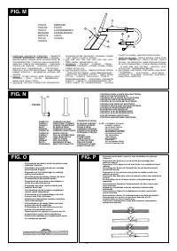
flows out of the ceramic nozzle
(FIG. M)
.
guarantee easy starts and to prevent the electrode from sticking to the piece.
TIG DC welding is suitable for all low- and high-carbon steels and the heavy metals,
copper, nickel, titanium and their alloys.
6.2.2 Procedure
For TIG DC welding with the electrode to the (-) terminal the electrode with 2% cerium
- Holding the mask IN FRONT OF THE FACE, strike the electrode tip on the workpiece
(grey band).
as if you were striking a match. This is the correct strike-up method.
It is necessary to sharpen the tungsten electrode axially on the grinding wheel, as
WARNING:
do not hit the electrode on the workpiece, this could damage the
shown in
FIG. N
,
making sure that the tip is perfectly concentric to prevent arc deviation.
electrode and make strike-up difficult.
It is important to carry out the grinding along the length of the electrode. This operation
- As soon as arc is ignited, try to maintain a distance from the workpiece equal to the
should be repeated periodically, depending on the amount of use and wear of the
diameter of the electrode in use. Keep this distance as much constant as possible for
electrode, or when the electrode has been accidentally contaminated, oxidised or used
the duration of the weld. Remember that the angle of the electrode as it advances
incorrectly.
should be of 20-30 grades.
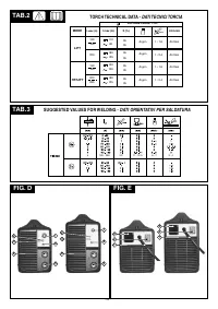
To achieve a good weld it is absolutely necessary to use the exact electrode diameter
- At the end of the weld bead, bring the end of the electrode backward, in order to fill the
with the exact current, see the table
(TAB.3).
weld crater, quickly lift the electrode from the weld pool to extinguish the arc.
The electrode usually protrudes from the ceramic nozzle by 2-3mm, but this may reach
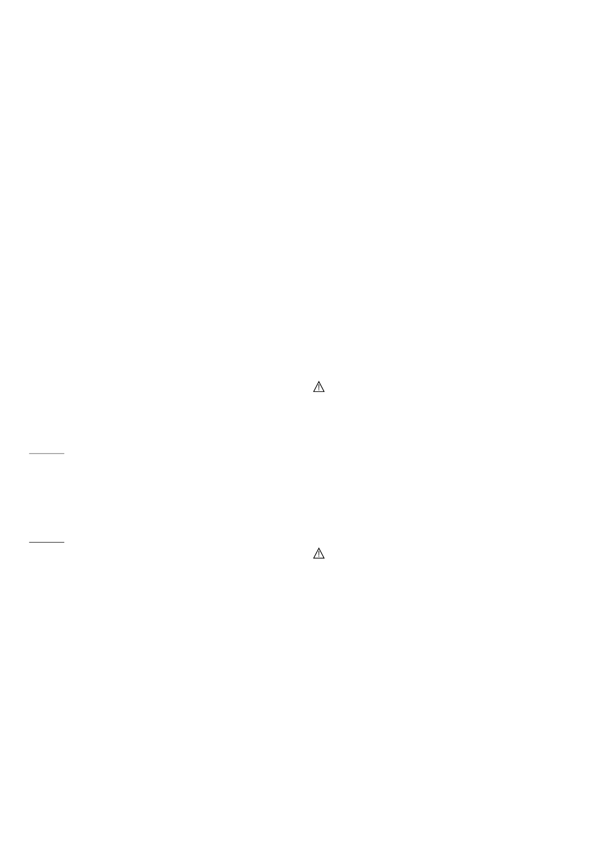
CHARACTERISTICS OF THE WELD BEAD (FIG. R)
8mm for corner welding.
Welding is achieved by fusion of the edges of the joint. For properly prepared thin pieces
7. MAINTENANCE
(up to about 1mm) weld material is not needed
(FIG. O)
.
_____________________________________________________________________________________________________________________
For thicker pieces it is necessary to use filler rods of the same composition as the base
material and with an appropriate diameter, preparing the edges correctly
(FIG. P)
. To
WARNING! BEFORE CARRYING OUT MAINTENANCE OPERATIONS MAKE
achieve a good weld the pieces should be carefully cleaned and free of oxidation, oil,
SURE THE WELDING MACHINE IS SWITCHED OFF AND DISCONNECTED FROM
grease, solvents etc.
THE MAIN POWER SUPPLY.
_____________________________________________________________________________________________________________________
6.1.2 HF and LIFT strike
7.1 ROUTINE MAINTENANCE
HF strike:
ROUTINE MAINTENANCE OPERATIONS CAN BE CARRIED OUT BY THE
The electric arc is struck without contact between the tungsten electrode and the piece
OPERATOR.
being welded, by means of a spark generated by a high frequency device. This strike
mode does not entail either tungsten inclusions in the weld pool or electrode wear and
gives an easy start in all welding positions.
7.1.1 Torch
Procedure:
- Do not put the torch or its cable on hot pieces; this would cause the insulating
Press the torch button, bringing the tip of the electrode close to the piece (2 -3mm), wait
materials to melt, making the torch unusable after a very short time.
for the arc strike transferred by the HF pulses and, when the arch has struck, form the
- Make regular checks on the gas pipe and connector seals.
weld pool on the piece and proceed along the joint.
- Accurately match collet and collet body with the selected electrode diameter in order
If there are difficulties in striking the arc even though the presence of gas is confirmed
to avoid overheating, bad gas diffusion and poor performance.
and the HF discharges are visible, do not insist for long in subjecting the electrode to HF
- At least once a day check the terminal parts of the torch for wear and make sure they
action, but check the integrity of the surface and the shape of the tip, dressing it on the
are assembled correctly: nozzle, electrode, electrode-holder clamp, gas diffuser.
grinding wheel if necessary. At the end of the cycle the current will fall at the slope down
- Before using the welding machine, always check the terminal parts of the torch for
setting.
wear and make sure they are assembled correctly: nozzle, electrode, electrode-
holder clamp, gas diffuser.
LIFT strike:
The electric arc is struck by moving the tungsten electrode away from the piece to be
7.2 EXTRAORDINARY MAINTENANCE
welded. This strike mode causes less electrical-radiation disturbance and reduces
EXTRAORDINARY MAINTENANCE OPERATIONS SHOULD BE CARRIED OUT
tungsten inclusions and electrode wear to a minimum.
ONLY AND EXCLUSIVELY BY SKILLED OR AUTHORISED ELECTRICAL-
Procedure:
MECHANICAL TECHNICIANS.
_____________________________________________________________________________________________________________________
Place the tip of the electrode on the piece, using gentle pressure. Press the torch button
right down (only for HF/LIFT models) and lift the electrode 2-3mm with a few moments'
WARNING! BEFORE REMOVING THE WELDING MACHINE PANELS AND
delay, thus striking the arc. Initially the welding machine supplies a current I
, after a
BASE
WORKING INSIDE THE MACHINE MAKE SURE THE WELDING MACHINE IS
few moments the welding current setting will be supplied. At the end of the cycle the
SWITCHED OFF AND DISCONNECTED FROM THE MAIN POWER SUPPLY
current will fall to zero at the slope down setting (only for HF/LIFT models).
OUTLET.
_____________________________________________________________________________________________________________________
6.1.3 Procedure
6.1.3.1 Welding modes for welding machines with LIFT strike
If checks are made inside the welding machine while it is live, this may cause
- Adjust the welding current to the desired value using the knob; if necessary adjust it
serious electric shock due to direct contact with live parts and/or injury due to
during welding to the actual heat transfer needed.
direct contact with moving parts.
- Make sure the gas outflow is correct.
- Inspect the welding machine regularly, with a frequency depending on use and the
- To interrupt welding, lift the electrode quickly from the piece.
dustiness of the environment, and remove the dust deposited on the transformer,
reactance and rectifier using a jet of dry compressed air (max. 10bar).
6.1.3.2 Welding modes for welding machines with HF/LIFT strike
- Do not direct the jet of compressed air on the electronic boards; these can be cleaned
TIG mode with 2T sequence:
with a very soft brush or suitable solvents.
- Press the torch button right down, strike the arc keeping at 2-3mm from the piece.
- At the same time make sure the electrical connections are tight and check the wiring
- Adjust the welding current to the desired value using the knob; if necessary adjust it
for damage to the insulation.
during welding to the actual heat transfer needed.
- At the end of these operations re-assemble the panels of the welding machine and
- Make sure the gas outflow is correct
screw the fastening screws right down.
- To interrupt welding release the torch button, causing the current to decrease to
- Never, ever carry out welding operations while the welding machine is open.
nothing gradually (if the SLOPE DOWN function is enabled) or immediate extinction
of the arc with subsequent post gas.
8. TROUBLESHOOTING
TIG mode with 4T sequence:
IN CASE OF UNSATISFACTORY FUNCTIONING, BEFORE SERVICING MACHINE
- The first time the button is pressed it will strike the arc with base current I
. When the
BASE
OR REQUESTING ASSISTANCE, CARRY OUT THE FOLLOWING CHECK:
button is released the current increases to the welding current value; this value is also
- Check that the welding current, which is regulated by the potentiometer with a
maintained when the button is released. If you keep the button pressed down the
graduated amp scale, is correct for the diamter and electrode type in use.
current will decrease according to the SLOPE DOWN function (if it has been set) to
- Check that when general switch is ON the relative lamp is ON. If this is not the case
reach the minimum welding current The minimum current will be maintained until the
then the problem is located on the mains (cables, plugs, outlets, fuses, etc.)
button is released to terminate the welding cycle and start the post gas phase.
- Check that the yellow led (ie. thermal protection interruption- either over or
If, on the other hand, you release the button while the SLOPE DOWN function is
undervoltage or short circuit) is not lit.
proceeding, the welding cycle will terminate immediately and the post gas phase will
- Check that the nominal intermittance ratio is correct. In case there is a thermal
start.
protection interruption, wait for the machine to cool down, check that the fan is
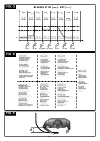
TIG mode with 4T sequence (BI-LEVEL) (only for TWIN CASE and 3-phase
working properly.
models):
- Check the mains voltage: if the value is too high or too low the welding machine will be
- 4T BI-LEVEL TIG mode (for the TWIN CASE welding machine with HF/LIFT strike) is
stopped.
only available with dual potentiometer remote control, I can be adjusted with the
B
- Check that there is no short-circuit at the output of the machine: if this is the case
Slope Down /Arc Force potentiometer of the welding machine. If there is no dual
eliminate the incovenience.
potentiometer control I is 25% of the current setting.
B
- Check that all connections of the welding circuit are correct, particularly that the work
- The first time the button is pressed it will strike the arc with the base current setting
clamp is well attached to the workpiece, with no interferring material or surface-
I
. When the button is released the current increases to the welding current value;
BASE
coverings (ie. Paint).
this value is also maintained when the button is released. Every time the button is
- Protective gas must be of appropriate type (Argon 99,5%) and quantity.
pressed after that (the time between pressure and release should be short) the
current will vary between the BI-LEVEL parameter setting I and the main current
B
value I .
A
If you keep the button pressed down the current will decrease according to the
- 7 -


