Сварочное оборудование Telwin TECHNOLOGY TIG 185 DC HF LIFT - инструкция пользователя по применению, эксплуатации и установке на русском языке. Мы надеемся, она поможет вам решить возникшие у вас вопросы при эксплуатации техники.
Если остались вопросы, задайте их в комментариях после инструкции.
"Загружаем инструкцию", означает, что нужно подождать пока файл загрузится и можно будет его читать онлайн. Некоторые инструкции очень большие и время их появления зависит от вашей скорости интернета.

1. GENERAL SAFETY CONSIDERATIONS FOR ARC WELDING ....................
5
5.1.2 Assembling the welding cable-electrode holder clamp ......................
6
5.2 HOW TO LIFT THE WELDING MACHINE ..................................................
6
2. INTRODUCTION AND GENERAL DESCRIPTION ........................................
5
5.3 POSITION OF THE WELDING MACHINE .................................................
6
2.1 INTRODUCTION ......................................................................................
5
5.4 CONNECTION TO THE MAIN POWER SUPPLY.......................................
6
2.2 OPTIONAL ACCESSORIES .....................................................................
5
5.4.1 Plug and socket ................................................................................
6
3. TECHNICAL DATA .........................................................................................
5
5.5 CONNECTION OF THE WELDING CABLES ............................................
6
3.1 DATA PLATE .............................................................................................
5
5.5.1 TIG welding ......................................................................................
6
3.2 OTHER TECHNICAL DATA .......................................................................
6
5.5.2 MMA WELDING ...............................................................................
7
4. DESCRIPTION OF THE WELDING MACHINE ...............................................
6
6. WELDING: DESCRIPTION OF THE PROCEDURE ..........................................
7
4.1 BLOCK DIAGRAM ....................................................................................
6
6.1.1 General principles ..................................................................................
7
4.1.1 Welding machine with LIFT strike......................................................
6
6.1.2 HF and LIFT strike ..................................................................................
7
4.1.2 Welding machine with HF/LIFT strike ................................................
6
6.1.3 Procedure ..............................................................................................
7
4.2 CONTROL DEVICES, ADJUSTMENT AND CONNECTION .....................
6
6.1.3.1 Welding modes for welding machines with LIFT strike ....................
7
4.2.1 COMPACT welding machine with LIFT strike ....................................
6
6.1.3.2 Welding modes for welding machines with HF/LIFT strike ..............
7
4.2.1.1 Front panel ..........................................................................
6
6.2 MMA WELDING ........................................................................................
7
4.2.1.2 Back panel...........................................................................
6
6.2.1 Comments .......................................................................................
7
4.2.2 Welding machine with HF/LIFT strike
................................................
6
6.2.2 Procedure ........................................................................................
7
4.2.2.1 Front panel ..........................................................................
6
7. MAINTENANCE ...............................................................................................
7
4.2.2.2 Back panel...........................................................................
6
7.1 ROUTINE MAINTENANCE .......................................................................
7
4.2.3 Remote control .................................................................................
6
7.1.1 Torch ................................................................................................
7
5. INSTALLATION ................................................................................................
6
7.2 EXTRAORDINARY MAINTENANCE ........................................................
7
5.1 ASSEMBLY ...............................................................................................
6
8. TROUBLESHOOTING ......................................................................................
7
5.1.1 Assembling the return cable-clamp...................................................
6
INDEX
ENGLISH
page
page
INVERTER WELDING MACHINES FOR TIG AND MMA WELDING DESIGNED FOR
INDUSTRIAL AND PROFESSIONAL USE.
Note: In the following text the term “welding machine" will be used.
- Class A equipment:
This welding machine conforms to technical product standards for exclusive use
1.
GENERAL SAFETY CONSIDERATIONS FOR ARC
in an industrial environment and for professional purposes. It does not assure
WELDING
compliance with electromagnetic compatibility in domestic dwellings and in
The operator should be properly trained to use the welding machine safely and
premises directly connected to a low-voltage power supply system feeding
should be informed about the risks related to arc welding procedures, the
buildings for domestic use.
associated protection measures and emergency procedures.
(Refer also to the “IEC TECHNICAL SPECIFICATION or CLC/TS 62081”:
INSTALLATION AND USE OF EQUIPMENT FOR ARC WELDING).
EXTRA PRECAUTIONS
WELDING OPERATIONS:
- In environments with increased risk of electric shock.
- In confined spaces.
-
Avoid direct contact with the welding circuit: the no-load voltage supplied by
- In the presence of flammable or explosive materials.
the welding machine can be dangerous under certain circumstances.
MUST BE evaluated in advance by an “Expert supervisor” and must always be
-
When the welding cables are being connected or checks and repairs are
carried out in the presence of other people trained to intervene in
carried out the welding machine should be switched off and disconnected
emergencies.
from the power supply outlet.
Technical protection measures MUST BE taken as described in 5.10; A.7; A.9.
-
Switch off the welding machine and disconnect it from the power supply outlet
of the “IEC TECHNICAL SPECIFICATION or CLC/TS 62081”.
before replacing consumable torch parts.
- The operator MUST NOT BE ALLOWED to weld in raised positions unless
-
Make the electrical connections and installation according to the safety rules
safety platforms are used.
and legislation in force.
- VOLTAGE BETWEEN ELECTRODE HOLDERS OR TORCHES: working with
-
The welding machine should be connected only and exclusively to a power
more than one welding machine on a single piece or on pieces that are
source with the neutral lead connected to earth.
connected electrically may generate a dangerous accumulation of no-load
-
Make sure that the power supply plug is correctly connected to the earth
voltage between two different electrode holders or torches, the value of which
protection outlet.
may reach double the allowed limit.
-
Do not use the welding machine in damp or wet places and do not weld in the
An expert coordinator must use measuring instruments to determine the
rain.
existence of a risk and should take suitable protection measures as detailed in
-
Do not use cables with worn insulation or loose connections.
5.9 of the “IEC TECHNICAL SPECIFICATION or CLC/TS 62081”.
RESIDUAL RISKS
-
Do not weld on containers or piping that contains or has contained flammable
- IMPROPER USE: it is hazardous to use the welding machine for any work other
liquid or gaseous products.
than that for which it was designed (e.g. de-icing mains water pipes).
-
Do not operate on materials cleaned with chlorinated solvents or near such
substances.
2. INTRODUCTION AND GENERAL DESCRIPTION
-
Do not weld on containers under pressure.
2.1 INTRODUCTION
-
Remove all flammable materials (e.g. wood, paper, rags etc.) from the working
This welding machine is a power source for arc welding, made specifically for TIG (DC)
area.
welding with HF or LIFT strike and MMA welding with coated electrodes (rutile, acid,
-
Provide adequate ventilation or facilities for the removal of welding fumes
basic).
near the arc; a systematic approach is needed in evaluating the exposure
The specific characteristics of this regulation system (INVERTER), i.e. high speed and
limits for the welding fumes, which will depend on their composition,
precise regulation, mean the welding machine gives excellent results.
concentration and the length of exposure itself.
Regulation with the “inverter” system at the input of the power supply line (primary)
-
Keep the gas bottle (if used) away from heat sources, including direct
means there is a drastic reduction in the volume of both the transformer and the levelling
sunlight.
reactance. This allows the construction of a welding machine with extremely reduced
weight and volume, enhancing its advantages of easy handling and transportation.
2.2 OPTIONAL ACCESSORIES
- Use adequate electrical insulation with regard to the electrode, the work piece
- MMA welding Kit.
- TIG welding Kit.
and any (accessible) earthed metal parts in the vicinity.
- Argon gas bottle adapter.
This is normally achieved by wearing gloves, shoes, head coverings and
- Pressure reducing valve with gauge.
clothing designed for this purpose and by using insulating platforms or mats.
- TIG welding torch.
- Always protect your eyes using masks or helmets with special actinic glass.
- Self-darkening mask: with fixed and adjustable glass.
Use special fire-resistant protective clothing and do not allow the skin to be
- Welding current return cable complete with earth clamp.
exposed to the ultraviolet and infrared rays produced by the arc; other people
- Manual remote control with 1 potentiometer.
in the vicinity of the arc should be protected by shields of non-reflecting
- Manual remote control with 2 potentiometers.
curtains.
- Pedal remote control.
- TIG Pulse remote control (if present).
- Gas connector and pipe for hook-up with Argon bottle.
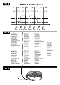
3. TECHNICAL DATA
- The flow of the welding current generates electromagnetic fields (EMF) around
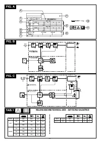
3.1 DATA PLATE (FIG. A)
the welding circuit.
The most important data regarding use and performance of the welding machine are
Electromagnetic fields can interfere with certain medical equipment (e.g. Pace-
summarised on the rating plate and have the following meaning:
makers, respiratory equipment, metallic prostheses etc.).
1-
Protection rating of the covering.
Adequate protective measures must be adopted for persons with these types of
2-
Symbol for power supply line:
medical apparatus. For example, they must be forbidden access to the area in
1~: single phase alternating voltage;
which welding machines are in operation.
3~: three phase alternating voltage.
This welding machine conforms to technical product standards for exclusive use
3-
Symbol
S
: indicates that welding operations may be carried out in environments with
in an industrial environment for professional purposes. It does not assure
heightened risk of electric shock (e.g. very close to large metallic volumes).
compliance with the basic limits relative to human exposure to electromagnetic
4-
Symbol for welding procedure provided.
fields in the domestic environment.
5-
Symbol for internal structure of the welding machine.
6-
EUROPEAN standard of reference, for safety and construction of arc welding
The operator must adopt the following procedures in order to reduce exposure to
machines.
electromagnetic fields:
7-
Manufacturer's serial number for welding machine identification (indispensable for
- Fasten the two welding cables as close together as possible.
technical assistance, requesting spare parts, discovering product origin).
- Keep head and trunk as far away as possible from the welding circuit.
8-
Performance of the welding circuit:
- Never wind welding cables around the body.
- U :
maximum no-load voltage (open welding circuit).
0
- Avoid welding with the body within the welding circuit. Keep both cables on the
- I /U :
current and corresponding normalised voltage that the welding machine can
2
2
same side of the body.
supply during welding.
- Connect the welding current return cable to the piece being welded, as close
- X :
Duty cycle: indicates the time for which the welding machine can supply the
as possible to the welding joint.
corresponding current (same column). It is expressed as %, based on a 10 minutes
- Do not weld while close to, sitting on or leaning against the welding machine
cycle (e.g. 60% = 6 minutes working, 4 minutes pause, and so on).
(keep at least 50 cm away from it).
If the usage factors (on the plate, referring to a 40°C environment) are exceeded,
- Do not leave objects in ferromagnetic material in proximity of the welding
the thermal safeguard will trigger (the welding machine will remain in standby until
circuit.
its temperature returns within the allowed limits).
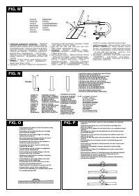
- Minimum distance d= 20 cm (Fig. S).
- A/V-A/V:
shows the range of adjustment for the welding current (minimum
maximum) at the corresponding arc voltage.
- 5 -


