Сварочное оборудование Telwin TECHNOLOGY TIG 185 DC HF LIFT - инструкция пользователя по применению, эксплуатации и установке на русском языке. Мы надеемся, она поможет вам решить возникшие у вас вопросы при эксплуатации техники.
Если остались вопросы, задайте их в комментариях после инструкции.
"Загружаем инструкцию", означает, что нужно подождать пока файл загрузится и можно будет его читать онлайн. Некоторые инструкции очень большие и время их появления зависит от вашей скорости интернета.


9-
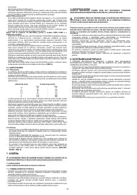
Technical specifications for power supply line:
-
ANTI STICK
protection:
automatically shuts down the welding machine if the
- U :
Alternating voltage and power supply frequency of welding machine (allowed
electrode sticks to the material being welded so that it can be removed manually
1
without damaging the electrode holder clamp.
limit ±10%).
11- Green LED
if on this means power is present at output, in the torch or on the
- I
:
Maximum current absorbed by the line.
1 max
electrode (only for 3-phase model).
- I
:
Effective current supplied.
1eff
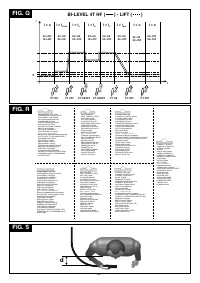
12- Potentiometer
BI-LEVEL current adjustment, 0 ÷ 100% scale (only for 3-phase
10-
:
Size of delayed action fuses to be used to protect the power line.
model).
11-
Symbols referring to safety regulations, whose meaning is given in chapter 1
“General safety considerations for arc welding”.
4.2.2.2 Back panel (FIG. G)
1 -
Power supply cable 2p + (
W
) for single phase, or 3p + (
W
) for 3-phase.
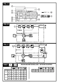
Note: The data plate shown above is an example to give the meaning of the symbols and
2 -
Main switch O/OFF - I/ON.
numbers; the exact values of technical data for the welding machine in your possession
3 -
Pipe fitting for gas tube connection (gas regulator cylinder - machine).
must be checked directly on the data plate of the welding machine itself.
4 -
Remote regulators connector.
3.2 OTHER TECHNICAL DATA
4.2.3 Remote control
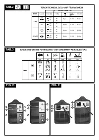
- WELDING MACHINE: see table 1 (TAB.1)
Using the special 14-pin connector on the back, it is possible to attach different types of
- TORCH:
see table 2 (TAB.2)
remote control to the welding machine. Each device will be recognised automatically
The welding machine weight is shown in table 1 (TAB. 1).
and can be used to adjust the following parameters:
- Remote control with one potentiometer:
4. DESCRIPTION OF THE WELDING MACHINE
turning the potentiometer knob will change the main current from the minimum to the
maximum. The main current is adjusted only and exclusively by the remote control.
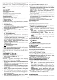
4.1 BLOCK DIAGRAM
- Pedal remote control:
The welding machine consists basically of power modules made on PCB's, optimised to
The current value is determined by the position of the pedal. In TIG 2-STROKE mode
achieve outstanding reliability and reduced maintenance.
pressing the pedal gives the start command to the machine instead of the torch
button (if present).
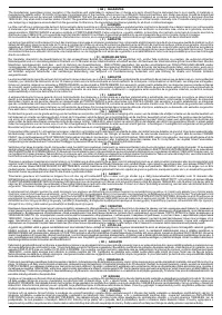
4.1.1 Welding machine with LIFT strike (FIG. B)
- Remote control with two potentiometers:
1- Input
single phase or 3-phase power supply line, rectifier unit and levelling
the first potentiometer adjusts the main current. The second potentiometer adjusts
capacitors
.
another parameter, depending on the active welding mode. When this potentiometer
2- Transistor switching bridge (IGBT) and drivers:
commutes the rectified power
is turned the display will show the changing value of the parameter (which can no
supply voltage to high frequency alternating voltage and adjusts the power
longer be controlled with the knob on the panel). In MMA mode it regulates ARC
according to the required welding current/voltage.
FORCE and in TIG mode, for welding machines with HF/LIFT strike it adjusts the
3- High frequency transformer:
the voltage converted by block 2 powers the primary
SLOPE DOWN.
winding; its function is to adjust the voltage and current to the values needed for the
- TIG-PULSE remote control (for the TWIN CASE welding machine and 3-phase
arc welding procedure and at the same time to form galvanic separation of the
model with HF/LIFT strike):
used for TIG welding with pulsed direct current, with the
welding circuit from the power supply line.
possibility of remote control adjustment of the most important parameters: base
4- Secondary rectifier bridge with levelling inductance:
commutes the alternating
current intensity, pulsed current intensity, duration of pulsed current, period of pulsed
voltage/current supplied by the secondary winding into very low ripple direct
current.
current/voltage.
This procedure gives greater control of heat transfer, making it possible to weld
5- Control and adjustment electronics:
they control the welding current value
materials that are thin or have a tendency for hot cracking, and it is also suited to
instantaneously and compare it with the operator's setting; they modulate the control
welding pieces of varying thickness and dissimilar steels such as stainless and low-
impulses from the IGBT drivers that make the adjustment.
carbon steel.
They determine the dynamic response of the current during electrode melting/fusion
The TIG PULSE remote control is only active in “TIG DC” 2-stroke and 4-stroke.
(instantaneous short circuits) and supervise the safety systems.
6- Welding machine operation control logic;
sets the welding cycles, controls the
actuators, supervises the safety systems.
7- Settings panel
and display of parameters and operating modes.
5. INSTALLATION
_____________________________________________________________________________________________________________________
8- Remote control.
WARNING! CARRY OUT ALL INSTALLATION OPERATIONS AND
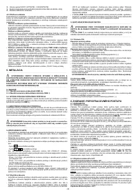
4.1.2 Welding machine with HF/LIFT strike (FIG. C)
ELECTRICAL CONNECTIONS WITH THE WELDING MACHINE COMPLETELY
1- Input:
1-phase power supply, rectifier unit and levelling capacitors.
SWITCHED OFF AND DISCONNECTED FROM THE POWER SUPPLY OUTLET.
2- Transistor switching bridge (IGBT) and drivers:
commutes the rectified power
supply voltage to high frequency alternating voltage and adjusts the power
THE ELECTRICAL CONNECTIONS MUST BE MADE ONLY AND EXCLUSIVELY BY
according to the required welding current/voltage.
AUTHORISED OR QUALIFIED PERSONNEL.
_____________________________________________________________________________________________________________________
3- High frequency transformer:
the voltage converted by block 2 powers the primary
winding; its function is to adjust the voltage and current to the values needed for the
5.1 ASSEMBLY
arc welding procedure and at the same time to form galvanic separation of the
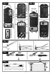
5.1.1 Assembling the return cable-clamp (FIG. H)
welding circuit from the power supply line.
5.1.2 Assembling the welding cable-electrode holder clamp (FIG. I)
4- Secondary rectifier bridge with levelling inductance:
commutes the alternating
voltage/current supplied by the secondary winding into very low ripple direct
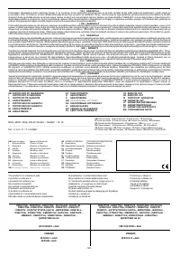
5.2 HOW TO LIFT THE WELDING MACHINE
current/voltage.
All the welding machines described in this handbook should be lifted using the handle or
5- Control and adjustment electronics:
they control the welding current value
strap supplied if provided for the particular model (fitted as described in
FIG. L
).
instantaneously and compare it with the operator's setting; they modulate the control
impulses from the IGBT drivers that make the adjustment.
5.3 POSITION OF THE WELDING MACHINE
They determine the dynamic response of the current during electrode melting/fusion
Choose the place to install the welding machine so that the cooling air inlets and outlets
(instantaneous short circuits) and supervise the safety systems.
are not obstructed (forced circulation by fan, if present); at the same time make sure that
6- Welding machine operation control logic;
sets the welding cycles, controls the
conductive dusts, corrosive vapours, humidity etc. will not be sucked into the machine.
actuators, supervises the safety systems.
Leave at least 250mm free space around the welding machine.
7- Settings panel
and display of parameters and operating modes.
_____________________________________________________________________________________________________________________
8-
HF strike generator.
WARNING! Position the welding machine on a flat surface with sufficient
9- Protective gas solenoid valve EV.
10-Remote control.
carrying capacity for its weight, to prevent it from tipping or moving hazardously.
_____________________________________________________________________________________________________________________
4.2 CONTROL DEVICES, ADJUSTMENT AND CONNECTION
4.2.1 COMPACT welding machine with LIFT strike
5.4 CONNECTION TO THE MAIN POWER SUPPLY
4.2.1.1 Front panel (FIG. D)
- Before making any electrical connection, make sure the rating data of the welding
1
- Positive quick plug (+) to connect welding cable.
machine correspond to the mains voltage and frequency available at the place of
2- GREEN LED :
Connection to the mains, machine ready to work.
installation.
3
-
YELLOW LED
: normally off, when ON it means that the welding current cannot flow
- The welding machine should only be connected to a power supply system with the
due to one of the following faults:
neutral conductor connected to earth.
-
Thermal protection:
inside the machine the temperature is excessive. The
- To ensure protection against indirect contact use residual current devices of the
machine is ON but does not deliver current until a normal temperature is reached.
following types:
Once this happens the re-start is automatic.
- Type A (
) for single phase machines;
-
Mains over/undervoltage protection:
the machine is blocked: the power supply
voltage is 15% above or below the rating plate value.
WARNING: Exceeding the
- Type B (
) for 3-phase machines.
upper voltage limit, as above, will cause serious damage to the device.
- To comply with the requirements of the EN 61000-3-11 (Flicker) standard we
-
ANTI STICK
protection:
automatically shuts down the welding machine if the
recommend connecting the welding machine to interface points of the power supply
electrode sticks to the material being welded so that it can be removed manually
that have an impedance of less than:
without damaging the electrode holder clamp.
- Zmax =0.21 ohm, for single phase welding machines with absorbed current greater
4 - TIG/MMA mode selector:
than 16A;
- Zmax =0.31 ohm, for single phase welding machines with absorbed current less
than or equal to 16A;
- TIG WELDING
- Zmax = 0.283 ohm, for 3-phase welding machine.
- The welding machine does not fall within the requisites of IEC/EN 61000-3-12
- MMA ELECTRODE WELDING
standard.
5 - Negative quick plug (-)
to connect welding cable.
Should it be connected to a public mains system, it is the installer's responsibility to
6-
Potentiometer
to regulate welding current with graduated scale in Amps, which
verify that the welding machine itself is suitable for connecting to it (if necessary,
also allows regulation during welding.
consult the distribution network company).
4.2.1.2 Back panel (FIG. E)
5.4.1 Plug and socket
1
- power supply cable 2p + (
W
).
- Single phase welding machines with absorbed currents that are less than or equal to
2
- General luminous switch
O
/OFF -
I
/ON.
16A are supplied from the factory with a power supply cable connected to a
3
- Remote control connector.
standardised plug (2P+T) 16A \250V
- Single phase welding machines with absorbed currents greater than 16A and 3-
4.2.2 Welding machine with HF/LIFT strike
phase machines are supplied with a power supply cable that is to be connected to an
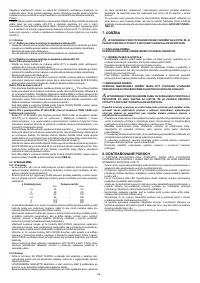
4.2.2.1 Front panel (FIG. F)
appropriately sized standardised plug, (2P+T) for single phase models and (3P+T) for
1-
Potentiometer
to regulate welding current with graduated scale in Amps, which
3-phase models. Prepare a power outlet protected by fuses or by an automatic circuit-
also allows regulation during welding.
breaker; the appropriate earth terminal should be connected to the earth conductor
2- TIG 2T, TIG 4T and MMA mode selector:
(yellow-green) of the power line.
3- GREEN LED :
Connection to the mains, machine ready to work.
- Table
(TAB.1)
shows the recommended delayed fuse sizes in amps, chosen
4- Selector with 2 positions for TIG start modes:
“HF” mode (high frequency,)
according to the max. nominal current supplied by the welding machine, and the
“LIFT” mode.
nominal voltage of the main power supply.
5- Potentiometer
for adjusting current down slope time in TIG mode. In MMA mode for
adjusting ARC FORCE. Graduated 0-100% scale.
5.5 CONNECTION OF THE WELDING CABLES
_____________________________________________________________________________________________________________________
6-
Positive quick plug (+)
to connect welding cable.
7-
Negative quick plug (-)
to connect welding cable.
WARNING! BEFORE MAKING THE FOLLOWING CONNECTIONS MAKE
8-
Pipe fitting
for connection of the TIG torch gas tube.
SURE THE WELDING MACHINE IS SWITCHED OFF AND DISCONNECTED FROM
9-
Connector
for connection torch pushbutton cable.
THE POWER SUPPLY OUTLET.
10-
YELLOW LED
: normally off, when ON it means that the welding current cannot flow
2
Table
(TAB. 1)
gives the recommended values for the welding cables (in mm )
due to one of the following faults:
depending on the maximum current supplied by the welding machine.
-
Thermal protection:
inside the machine the temperature is excessive. The
_____________________________________________________________________________________________________________________
machine is ON but does not deliver current until a normal temperature is reached.
Once this happens the re-start is automatic.
5.5.1 TIG welding
-
Mains over/undervoltage protection:
the machine is blocked: the power supply
Connecting the torch
voltage is 15% above or below the rating plate value.
WARNING: Exceeding the
- Insert the torch current cable into the appropriate quick terminal (-). Connect the
upper voltage limit, as above, will cause serious damage to the device.
three-pin connector (torch button) to the appropriate socket (if present). Connect the
- 6 -


