Кондиционеры Daikin EWAQ-F-SL - инструкция пользователя по применению, эксплуатации и установке на русском языке. Мы надеемся, она поможет вам решить возникшие у вас вопросы при эксплуатации техники.
Если остались вопросы, задайте их в комментариях после инструкции.
"Загружаем инструкцию", означает, что нужно подождать пока файл загрузится и можно будет его читать онлайн. Некоторые инструкции очень большие и время их появления зависит от вашей скорости интернета.


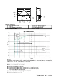

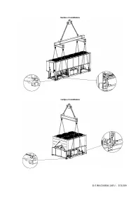

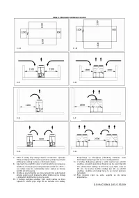


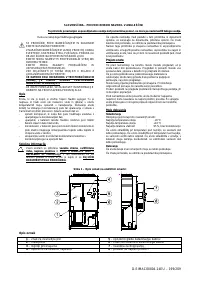
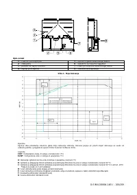

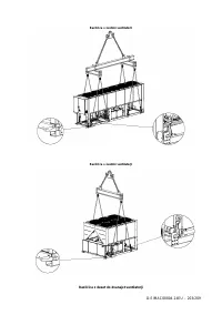
D-EIMAC00804-14EU - 17/209
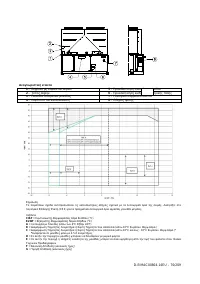
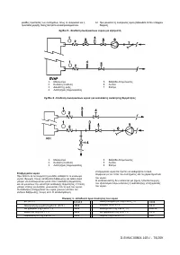
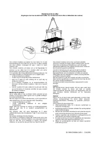
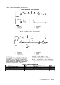
Evaporator
and
recovery
exchangers
anti-freeze
protection
All evaporators are supplied with a thermostatically controlled
anti-freeze electrical resistance, which provides adequate anti-
freeze protection at temperatures as low as –25°C. However,
unless the heat exchangers are completely empty and cleaned
with anti-freeze solution, additional methods should also be
used against freezing.
Two or more of below protection methods should be
considered when designing the system as a whole:
−
Continuous water flow circulation inside piping and
exchangers
−
Addition of an appropriate amount of glycol inside the
water circuit
−
Additional heat insulation and heating of exposed piping
−
Emptying and cleaning of the heat exchanger during the
winter season
It is the responsibility of the installer and/or of local
maintenance personnel to ensure that described anti-freeze
methods are used. Make sure that appropriate anti-freeze
protection is maintained at all times. Failing to follow the
instructions above could result in unit damage. Damage
caused by freezing is not covered by the warranty.
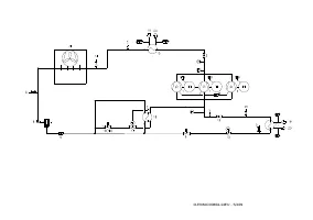
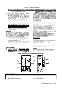
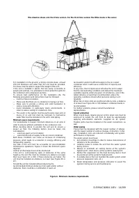
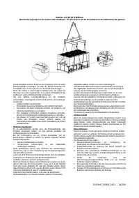
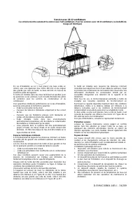
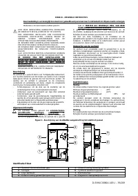
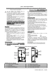
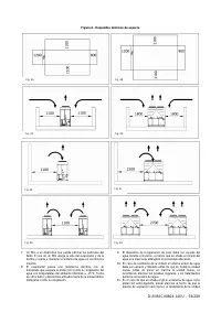
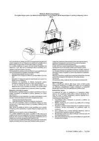
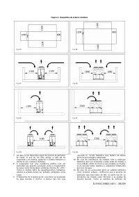
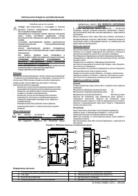
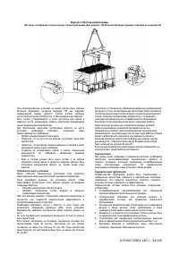
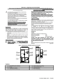
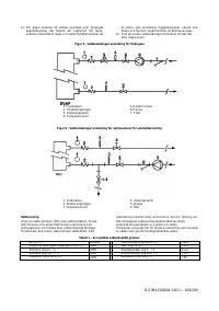
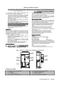
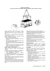
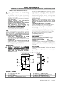
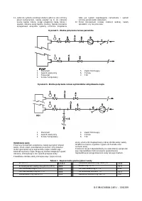
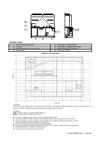
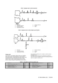
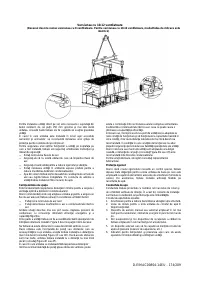
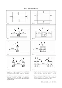
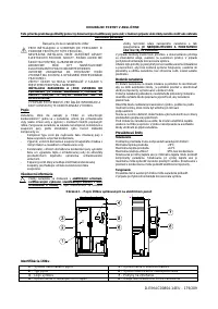
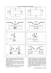
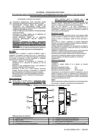
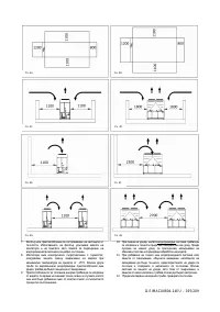
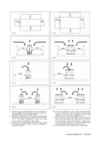
Installing the flow switch
To ensure sufficient water flow through the evaporator, it is
essential that a flow switch be installed on the water circuit.
The flow switch can be installed either on the inlet or outlet
water piping. The purpose of the flow switch is to stop the unit
in the event of interrupted water flow, thus protecting the
evaporator from freezing.
The manufacturer offers, as optional, a flow switch that has
been selected for this purpose.
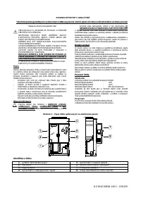
This paddle-type flow switch is suitable for heavy-duty outdoor
applications (IP67) and pipe diameters in the range of 1” to 6”.
The flow switch is provided with a clean contact which must be
electrically connected to terminals shown in the wiring
diagram.
Flow switch has to be tune to intervene when the evaporator
water flow is lower than 50% of nominal flow rate.
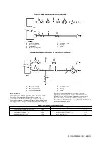
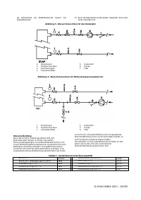
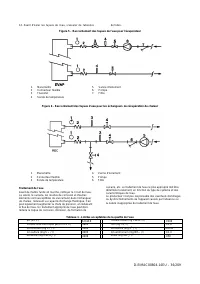
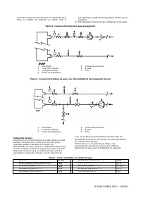
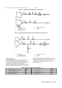
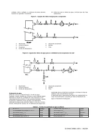
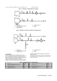
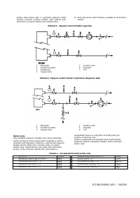
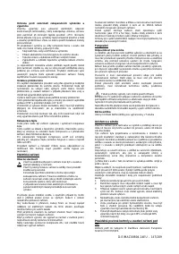
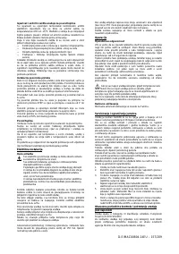
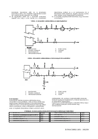
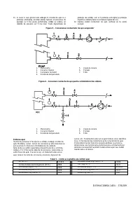
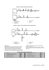
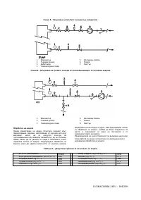
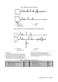
Heat recovery
Units may be optionally equipped with heat recovery system.
This system in made by a water cooled heat exchanger
located on the compressors discharge pipe and a dedicated
managment of condensing pressure.
To gurantee compressor operation within its envelope, units
with heat recovery cannot operate with water temperature of
the heat recovery water lower than 28°C.
It is a responsability of plant designer and chiller installer to
gurantee the respect of this value (e.g. using recirculating
bypass valve)
Electrical Installation
General specifications
All electrical connections to the unit must be carried out
in compliance with laws and regulations in force.
All installation, management and maintenance activities
must be carried out by qualified personnel.
Refer to the specific wiring diagram for the unit you have
bougth. Should the wiring diagram not be on the unit or
should it have been lost, please contact your
manufacturer representative, who will send you a copy.
In case of discrepance between wiring diagram and
electrical panel/cables, please contact the manufacturer
representative.
Only use copper conductors. Failure to use copper conductors
could result in overheating or corrosion at connection points
and could damage the unit.
To avoid interference, all control wires must be connected
separately from the power cables. Use different electrical
passage ducts for this purpose.
Before servicing the unit in any way, open the general
disconnecting switch on the unit’s main power supply.
When the unit is off but the disconnecting switch is in the
closed position, unused circuits are live, as well.
Never open the terminal board box of the compressors before
having opened the unit’s general disconnecting switch.
Contemporaneity of single-phase and three-phase loads and
unbalance between phases could cause leakages towards
ground up to 150mA, during the normal operation of the units
of the series.
If the unit includes devices that cause superior harmonics (like
VFD and phase cut), the leakage towards ground could
increases to very higher values (about 2 Ampere).
The protections for the power supply system have to be
designed according to the above mentioned values.
Operation
Operator’s responsibilities
It is essential that the operator is appropriately trained and
becomes familiar with the system before operating the unit. In
addition to reading this manual, the operator must study the
microprocessor operating manual and the wiring diagram in
order to understand start-up sequence, operation, shutdown
sequence and operation of all the safety devices.
During the unit’s initial start-up phase, a technician authorized
by the manufacturer is available to answer any questions and
to give instructions as to the correct operating procedures.
The operator must keep a record of operating data for every
installed unit. Another record should also be kept of all the
periodical maintenance and servicing activities.
If the operator notes abnormal or unusual operating conditions,
he is advised to consult the technical service authorized by the
manufacturer.
If all power to the unit is turned off, the compressor
heaters will become inoperable. Once power is resumed to the
unit, the compressor and oil separator heaters must be
energized a minimum of 12 hours before attempting to start the
unit.
Failure to do so can damage the compressors due to
excessive accumulation of liquid in the compressor.
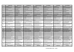
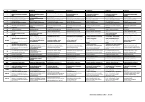
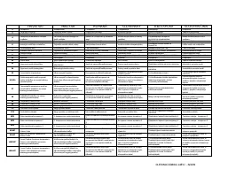
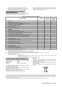
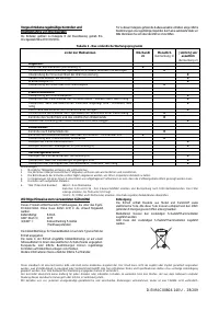
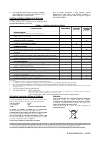
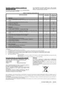
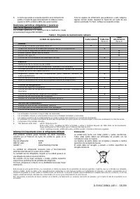
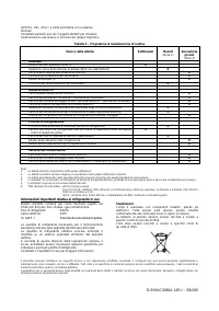
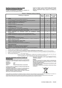
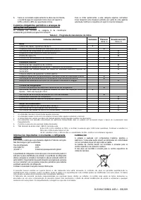
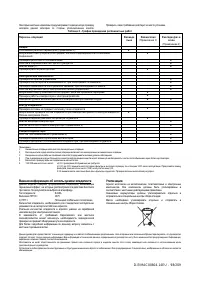
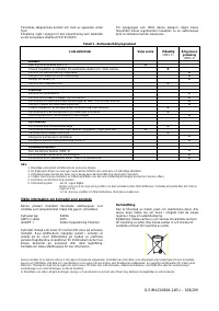
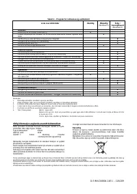
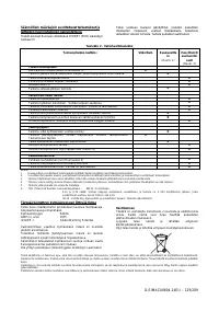
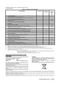
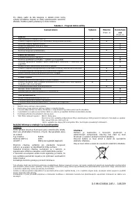
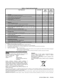
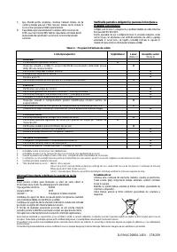
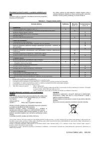
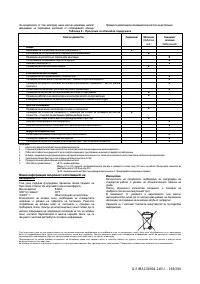
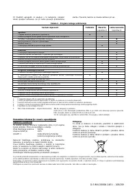
Routine maintenance
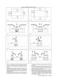
Minimum maintenance activities are listed in
Table 2
Service and limited warramty
All units are factory-tested and guaranteed for 12 months as of
the first start-up or 18 months as of delivery.
These units have been developed and constructed according
to high quality standards ensuring years of failure-free
operation. It is important, however, to ensure proper and
periodical maintenance in accordance with all the procedures
listed in this manual and with good practice of machines
maintenance.
We strongly advise stipulating a maintenance contract with a
service authorized by the manufacturer in order to ensure
efficient and problem-free service, thanks to the expertise and
experience of our personnel.
It must also be taken into consideration that the unit requires
maintenance also during the warranty period.
It must be borne in mind that operating the unit in an
inappropriate manner, beyond its operating limits or not
performing proper maintenance according to this manual can
void the warranty.
Observe the following points in particular, in order to conform
to warranty limits:
1.
The unit cannot function beyond the specified limits
2.
The electrical power supply must be within the voltage
limits and without voltage harmonics or sudden changes.
3.
The three-phase power supply must not have un
unbalance between phases exceeding 3%. The unit must
stay turned off until the electrical problem has been
solved.
4.
No safety device, either mechanical, electrical or
electronic must be disabled or overridden.
5.
The water used for filling the water circuit must be clean
and suitably treated. A mechanical filter must be installed
at the point closest to the evaporator inlet.


