Электропилы Bosch GCM 10 J - инструкция пользователя по применению, эксплуатации и установке на русском языке. Мы надеемся, она поможет вам решить возникшие у вас вопросы при эксплуатации техники.
Если остались вопросы, задайте их в комментариях после инструкции.
"Загружаем инструкцию", означает, что нужно подождать пока файл загрузится и можно будет его читать онлайн. Некоторые инструкции очень большие и время их появления зависит от вашей скорости интернета.


English |
25
Bosch Power Tools
1 609 92A 0XH | (12.12.14)
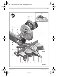
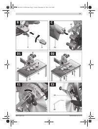
Operation
Before any work on the machine itself, pull the mains
plug.
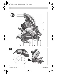
Transport Safety (see figure F)
The transport safety-lock
24
enables easier handling of the
machine when transporting to various working locations.
Releasing the Machine (Working Position)
– Push the tool arm by the handle
2
down a little in order to
relieve the transport safety-lock
24
.
– Pull the transport safety-lock
24
completely outward.
– Guide the tool arm slowly upward.
Note:
When working, pay attention that the transport safety-
lock is not pushed inwards. Otherwise, the tool arm cannot be
lowered to the requested depth.
Securing the Machine (Transport Position)
– Press lever
1
and at the same time, push the tool arm by
handle
2
downward until the transport safety-lock
24
can
be pushed completely inward.
The tool arm is now securely locked for transport.
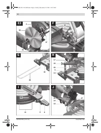
Mounting the Extension Bars (see figure G)
Long workpieces must be underlaid or supported at their free
end.
To extend the saw table additionally, extension bars can be
mounted both to the left or right of the power tool.
– Insert the extension bars
38
on both sides of the power
tool to the stop in the drill holes
16
intended for this pur-
pose.
– Tighten the screws for securing the extension bars.
Clamping the Workpiece (see figure H)
To ensure optimum working safety, the workpiece must
always be firmly clamped.
Do not saw workpieces that are too small to clamp.
– Press the workpiece firmly against the fence
5
.
– Insert the material clamp
17
provided into one of the holes
14
intended for it.
– Loosen the wing bolt
39
and adapt the material clamp to
the workpiece. Tighten the wing bolt again.
– Firmly clamp the workpiece by turning the threaded rod
40
in clockwise direction.
Loosening the Workpiece
– To release the material clamp, turn the threaded rod
40
in
anticlockwise direction.
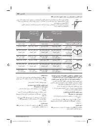
Adjusting the Cutting Angle
Before any work on the machine itself, pull the mains
plug.
To ensure precise cuts, the basic adjustment of the machine
must be checked and adjusted as necessary after intensive
use (see “Checking and Adjusting the Basic Adjustment”,
page 27).
Always tighten the locking knob 8 firmly before saw-
ing.
Otherwise the saw blade can become wedged in the
workpiece.
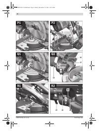
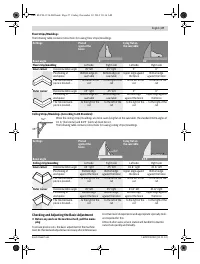
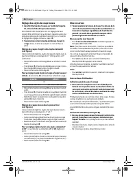
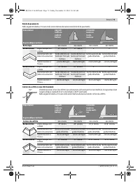
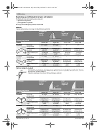
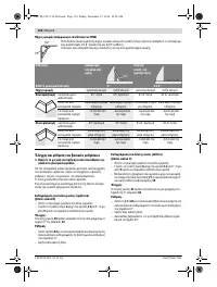
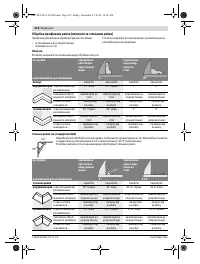
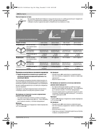
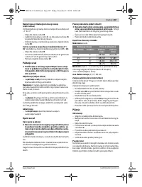
Adjusting Mitre Angles (see figure I)
The mitre angle can be set in the range from 47 ° (left side) to
47 ° (right side).
– Loosen the locking knob
8
in case it is tightened.
– Pull the lever
9
and turn the saw table
6
until the desired
mitre angle is indicated on the angle indicator
10
.
– Tighten the locking knob
8
again.
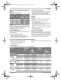
For quick and precise setting of often used mitre angles,
detents
11
are provided on the saw table:
– Loosen the locking knob
8
in case it is tightened.
– Pull lever
9
and rotate the saw table
6
left or right to the re-
quested detent.
– Release the lever again. The lever must be felt to engage in
the detent.
– Tighten the locking knob
8
again.
Adjusting Bevel Angles (see figure J)
The bevel angle can be set in the range from –2 ° to 47 °.
– Loosen the lock lever
19
.
– Tilt the tool arm by the handle
2
until the angle indicator
41
indicates the desired bevel angle.
– Hold the tool arm in this position and retighten the clamp-
ing lever
19
.
For quick and precise setting of the standard angles 0 °
and 45 °
, factory-set stop screws (
27
and
18
) have been pro-
vided for.
– Loosen the lock lever
19
.
– For this, tilt the tool arm by the handle
2
to the stop toward
the right (0 °) or to the stop toward the left (45 °).
– Retighten the lock lever
19
again.
Starting Operation
Observe correct mains voltage! The voltage of the pow-
er source must agree with the voltage specified on the
nameplate of the machine. Power tools marked with
230 V can also be operated with 220 V.
Switching On (see figure K)
– To
start
the machine, press the On/Off switch
3
and keep
it pressed.
Note:
For safety reasons, the On/Off switch
3
cannot be
locked; it must remain pressed during the entire operation.
The tool arm can only be guided downward when pressing
lever
1
.
– For
sawing
, you must additionally press lever
1
in addition
to actuating the On/Off switch
3
.
To save energy, only switch the power tool on when using it.
Switching Off
– To
switch off
the machine, release the On/Off switch
3
.
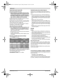
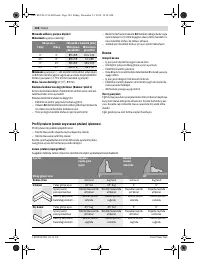
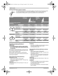
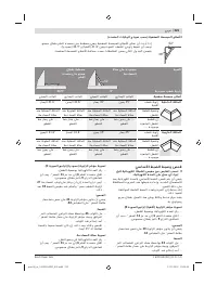
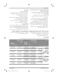
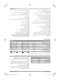
Left
Right
0 °
15 °; 22.5 °; 30 °; 45 °
15 °; 22.5 °; 30 °; 45 °
OBJ_BUCH-1156-002.book Page 25 Friday, December 12, 2014 10:16 AM
Содержание
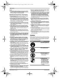
- 192 Безопасность людей
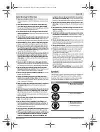
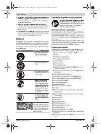
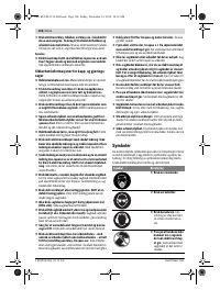
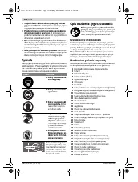
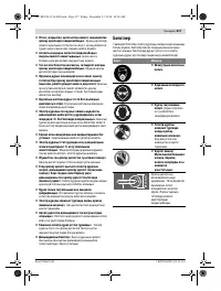
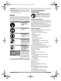
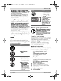
- 193 Не становитесь на электроинструмент.; Символы; Символ
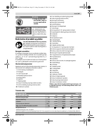
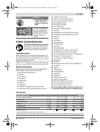
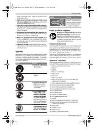
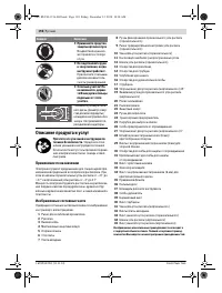
- 194 Описание продукта и услуг; Применение по назначению
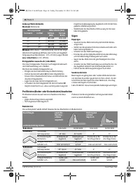
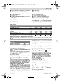
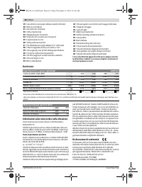
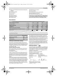
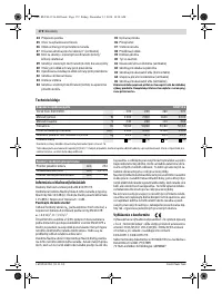
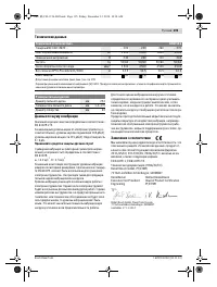
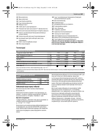
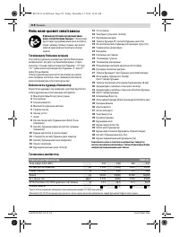
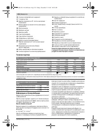
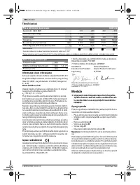
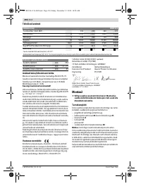
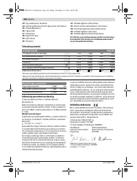
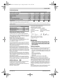
- 195 Технические данные; Применяйте средства защиты органов слуха!; Заявление о соответствии; Торцовочно-усовочная пила; Размеры пильных дисков
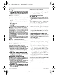
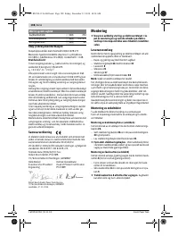
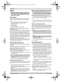
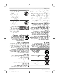
- 196 Сборка; Комплект поставки; Монтаж на верстаке производства Bosch; Отсос пыли и стружки
- 197 Внешняя система пылеотсоса; Работа с инструментом
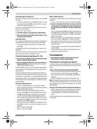
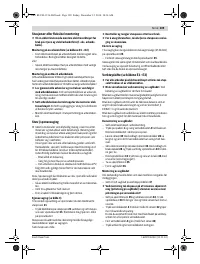
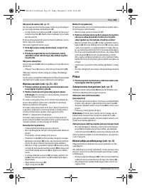
- 198 Снятие крепления детали; Настройка угла распила; включения
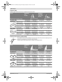
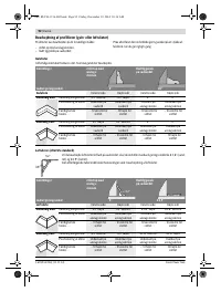
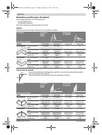
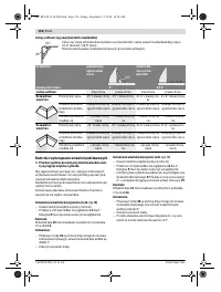
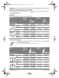
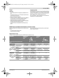
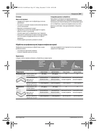
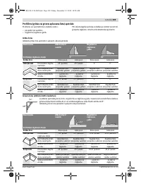
- 199 Указания по применению; Общие указания для пиления; Пиление; Торцование
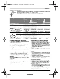
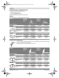
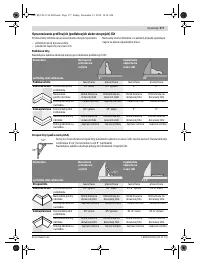
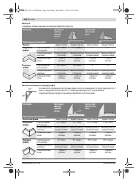
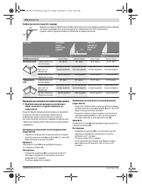
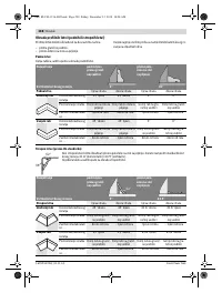
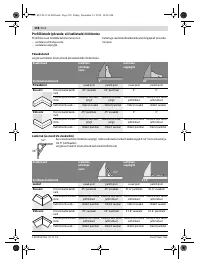
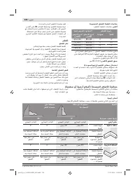
- 200 Плинтусы
- 201 Основные настройки – контроль и коррекция; Настройка упорной планки
- 202 Транспортировка; Техобслуживание и сервис; Техобслуживание и очистка; Очистка; Принадлежности; Россия
- 203 Казахстан; Утилизация


