Электропилы Bosch GCM 10 J - инструкция пользователя по применению, эксплуатации и установке на русском языке. Мы надеемся, она поможет вам решить возникшие у вас вопросы при эксплуатации техники.
Если остались вопросы, задайте их в комментариях после инструкции.
"Загружаем инструкцию", означает, что нужно подождать пока файл загрузится и можно будет его читать онлайн. Некоторые инструкции очень большие и время их появления зависит от вашей скорости интернета.


English |
23
Bosch Power Tools
1 609 92A 0XH | (12.12.14)
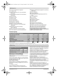
Noise/Vibration Information
Sound emission values determined according to
EN 61029-2-9.
Typically the A-weighted noise levels of the product are:
Sound pressure level 102 dB(A); Sound power level
115 dB(A). Uncertainty K = 3 dB.
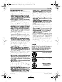
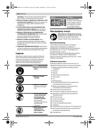
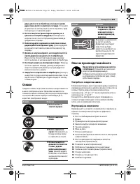
Wear hearing protection!
Vibration total values a
h
(triax vector sum) and uncertainty K
determined according to EN 61029:
a
h
= 3.0 m/s
2
, K = 1.5 m/s
2
.
The vibration emission level given in this information sheet
has been measured in accordance with a standardised test
given in EN 61029 and may be used to compare one tool with
another. It may be used for a preliminary assessment of expo-
sure.
The declared vibration emission level represents the main ap-
plications of the tool. However if the tool is used for different
applications, with different accessories or poorly maintained,
the vibration emission may differ. This may significantly in-
crease the exposure level over the total working period.
An estimation of the level of exposure to vibration should also
take into account the times when the tool is switched off or
when it is running but not actually doing the job. This may sig-
nificantly reduce the exposure level over the total working pe-
riod.
Identify additional safety measures to protect the operator
from the effects of vibration such as: maintain the tool and the
accessories, keep the hands warm, organisation of work pat-
terns.
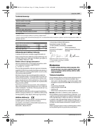
Declaration of Conformity
We declare under our sole responsibility that the product de-
scribed under “Technical Data” is in conformity with all rele-
vant provisions of the directives 2011/65/EU, 2014/30/EU,
2006/42/EC including their amendments and complies with
the following standards: EN 61029-1, EN 61029-2-9.
Technical file (2006/42/EC) at:
Robert Bosch GmbH, PT/ETM9,
70764 Leinfelden-Echterdingen, GERMANY
Robert Bosch GmbH, Power Tools Division
70764 Leinfelden-Echterdingen, GERMANY
Leinfelden, 27.11.2014
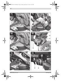
Assembly
Avoid unintentional starting of the machine. During as-
sembly and for all work on the machine, the power plug
must not be connected to the mains supply.
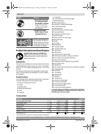
Delivery Scope
Before starting the operation of the machine for the first time,
check if all parts listed below have been supplied:
– Mitre saw with mounted saw blade
– Metal bar of tilt protector
26
with fastening screw
31
– Locking knob
8
– Dust bag
21
– Material clamp
17
– Hex key/cross-head screwdriver
28
Note:
Check the power tool for possible damage.
Before further use of the machine, check that all protective
devices are fully functional. Any lightly damaged parts must
be carefully checked to ensure flawless operation of the tool.
All parts must be properly mounted and all conditions fulfilled
that ensure faultless operation.
Damaged protective devices and parts must be immediately
replaced by an authorised service centre.
Mounting Individual Components
Carefully remove all parts provided from their packaging.
Remove all packing material from the power tool and the ac-
cessories provided.
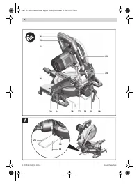
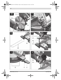
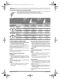
Mounting the Tilt Protector (see figure A)
Before using the power tool for the first time, the tilt protector
26
must be mounted.
– Insert the metal bar of tilt protector
26
into the drill holes
30
of base plate intended for this purpose.
– Affix the metal bar of tilt protector with fastening screw
31
.
Never remove the tilt protector.
Without the use of the
tilt protector, the machine does not stand safely and can
tip over, especially when sawing at maximum mitre/bevel
angles.
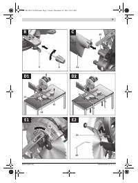
Mounting the Locking Knob (see figure B)
Before putting the mitre saw into operation for the first time,
the locking knob
8
(for locking variable horizontal mitre an-
gles) must be mounted.
– Remove the screw mounted in the locking-knob hole for
shipping purposes.
– Screw the locking knob
8
into the corresponding drill hole
above the lever
9
.
Always tighten the locking knob 8 firmly before saw-
ing.
Otherwise the saw blade can become wedged in the
workpiece.
Stationary or Flexible Mounting
To ensure safe handling, the machine must be mounted
on a level and stable surface (e. g., workbench) prior to
using.
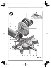
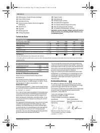
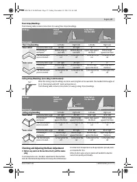
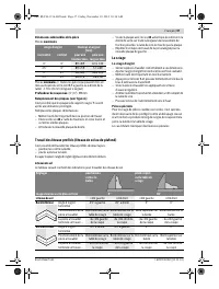
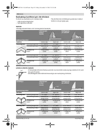
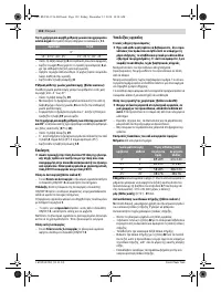
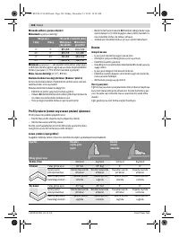
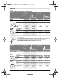
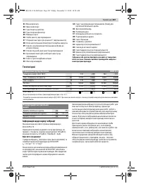
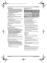
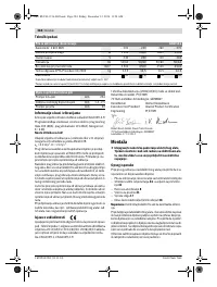
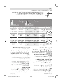
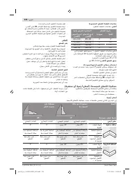
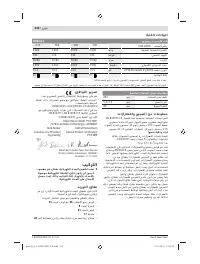
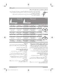
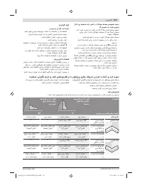
Dimension of suitable saw blades
Saw blade diameter
mm
254
Blade body thickness
mm
1.4 – 2.5
Mounting hole diameter
mm
30
Henk Becker
Executive Vice President
Engineering
Helmut Heinzelmann
Head of Product Certification
PT/ETM9
OBJ_BUCH-1156-002.book Page 23 Friday, December 12, 2014 10:16 AM
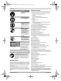
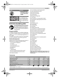
Содержание
- 192 Безопасность людей
- 193 Не становитесь на электроинструмент.; Символы; Символ
- 194 Описание продукта и услуг; Применение по назначению
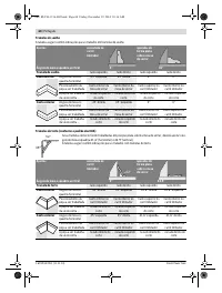
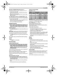
- 195 Технические данные; Применяйте средства защиты органов слуха!; Заявление о соответствии; Торцовочно-усовочная пила; Размеры пильных дисков
- 196 Сборка; Комплект поставки; Монтаж на верстаке производства Bosch; Отсос пыли и стружки
- 197 Внешняя система пылеотсоса; Работа с инструментом
- 198 Снятие крепления детали; Настройка угла распила; включения
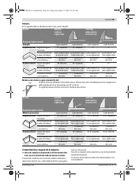
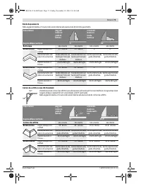
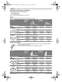
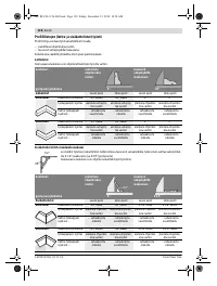
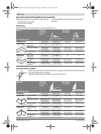
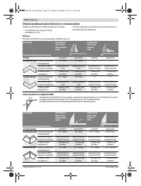
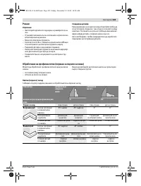
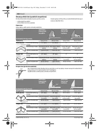
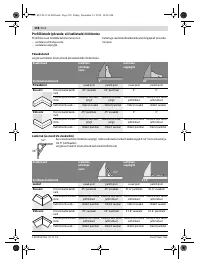
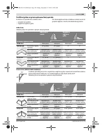
- 199 Указания по применению; Общие указания для пиления; Пиление; Торцование
- 200 Плинтусы
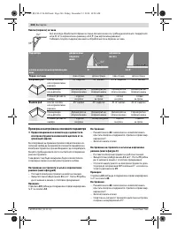
- 201 Основные настройки – контроль и коррекция; Настройка упорной планки
- 202 Транспортировка; Техобслуживание и сервис; Техобслуживание и очистка; Очистка; Принадлежности; Россия
- 203 Казахстан; Утилизация


