Сварочное оборудование Telwin INVERPULSE 425 MIG TIG MMA - инструкция пользователя по применению, эксплуатации и установке на русском языке. Мы надеемся, она поможет вам решить возникшие у вас вопросы при эксплуатации техники.
Если остались вопросы, задайте их в комментариях после инструкции.
"Загружаем инструкцию", означает, что нужно подождать пока файл загрузится и можно будет его читать онлайн. Некоторые инструкции очень большие и время их появления зависит от вашей скорости интернета.


- 8 -
In MIG-MAG pulse arc mode the parameter determines arc pinch-off. The higher
the value the more concentrated will be the arc during welding. In a welding
mode using two current levels (bi-level, pulse on pulse or T
start
) arc pinch-off has
the same setting for both levels (+1% / -1%).
In MIG-MAG Pulse on Pulse mode the parameter can be used to adjust the
duration of secondary welding current (adjustment range 0.1-10 seconds and
LED
(15b)
on).
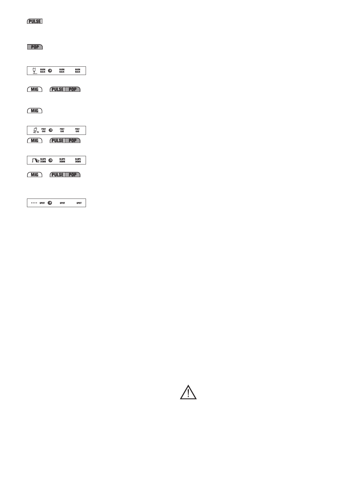
10e-
Wire BURN-BACK time when welding stops.
This parameter is used to adjust wire burn-back time at the end of welding.
When setting a MIG-MAG synergic programme this parameter is used to set the
correction to be made to BURN-BACK TIME as calculated in synergy (range
from -1% to +1%, LED
(15c)
on).
Short arc “PRG 0”
An appropriate setting will prevent the wire from sticking to the piece in manual
mode (adjustment range 0.001-1 seconds and LED
(15b)
on).
10f-
POST-GAS
It allows adjusting the time for which protective gas will flow after welding stops
(adjustment range 0.1-10 seconds and LED
(15b)
on).
10g-
Welding current SLOPE DOWN.
This is enabled only and exclusively when using MIG-MAG SHORT ARC,
PULSE ARC and PULSE on PULSE synergic programmes.
It is used to reduce the current gradually when the torch button is released
(adjustment range 0-3 seconds and LED
(15b)
on).
10h-
SPOT WELDING TIME.
This is enabled only and exclusively if “SPOT” mode has been selected with key
(8)
. It is used for MIG-MAG spot welding, with welding time control (adjustment
range 0.1-10 seconds and LED
(15b)
on).
11- Key for manual activation of gas solenoid valve.
This button causes gas outflow (piping discharge – flow rate adjustment) without
having to operate the torch button; the action of the button is momentary.
12- Key for manual wire feed.
This button is used to feed the wire along the torch hose without having to
operate the torch button; the action is momentary and feed rate is fixed.
13- Encoder knob for adjusting welding parameters (see 10a-10h).
14- Encoder knob.
The knob adjusts:
- Welding current I
2
(LED
(16a)
on).
- The wire feed rate (LED
(16c)
on)
- The thickness of the piece used in welding (LED
(16b)
on)
In a welding mode using two current levels (bi-level, pulse on pulse or T
start
), with
LED
(10b)
on the knob adjusts:
- Welding current I
1
(LED
(16a)
on) for the secondary level.
- Wire feed rate for the secondary welding level (LED
(16c)
on).
- The thickness of the piece used in welding (LED
(16b)
on) for the secondary
level.
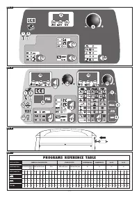
15- 3-digit alphanumeric display.
This shows:
- welding parameter values (see from
(10a)
to
(10h)
) in no-load operation.
- the actual arc voltage during welding.
NOTE: when welding stops, the display automatically switches to the setting
value.
- an alarm indicator (see point 1).
15a, 15b, 15c- LED’s indicating current unit of measurement (volts,
seconds, percentage).
16- 3-digit alphanumeric display.
This shows:
- the value of the setting made using the encoder knob
(14)
.
- the actual current during welding.
NOTE: when welding stops, the display automatically switches to the setting
value.
- an alarm indicator (see point 1).
16a, 16b, 16c- LED’s indicating current unit of measurement (current in
amps (A), thickness in millimetres (mm) and wire feed rate metres/minute
(m/min)).
17- Key for selecting unit of measurement - Amps/Thickness in m/min (LED’s
(16a)(16b) (16c)).
In synergic MIG/MAG programs it is used to set weld material thickness, welding
current and wire feed rate respectively, using the encoder
(14)
.
The setting for each individual parameter (e.g. material thickness) automatically
defines the values of the other parameters (e.g. welding current and wire feed
rate).
In “PRG 0” manual selection: it is only possible to adjust the wire feed rate (LED
(16c)
on).
4.3 RECALLING AND STORING PROGRAMS
4.3.1 RECALLING MANUFACTURER’S PRE-STORED PROGRAMS
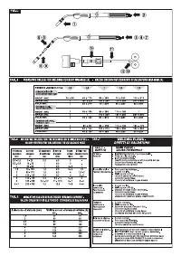
4.3.1.1 MIG-MAG SYNERGIC programs
The welding machine is designed with
36 stored synergic programs,
as specified in
the table
(TAB.3), which must be consulted when selecting a suitable program
for the type of welding to be carried out.
A particular program is selected by pressing the “PRG” program repeatedly and the
corresponding number, between “0” and “36” will be shown on the display (the number
“0” does not have a corresponding synergic program but is for operating in manual
mode, as described in the next paragraph).
Note: In a synergic program, it is essential to first select the desired transfer
mode, PULSE ARC or SHORT/SPRAY ARC, using the appropriate key (see FIG.
D (7)).
Note:
All types of wire that are not shown in the table can be used in manual
mode “PRG 0”.
4.3.1.2 OPERATION IN MANUAL MODE (“PRG 0”)
Operation in manual mode corresponds to the number “0” on the display and is only
active if the SHORT/SPRAY ARC transfer mode has been selected previously
(see
FIG. D (7)).
In this mode, as there will be no synergy, the operator should set all welding parameters
manually.
Warning!
The operator can set all the parameters freely therefore it is possible to set
values that are incompatible with a correct welding procedure.
Note: it is NOT possible to use PULSE ARC transfer mode when manual is
selected.
4.3.2 STORING AND RECALLING CUSTOMISED MIG-MAG PROGRAMS
4.3.2.1 Introduction
The welding machine can be used to (SAVE) customised work programs relating to
a set of valid parameters for a particular welding job. Each stored program can be
recalled (RECALL) at any time so that the user finds the welding machine “ready-to-
use” for a specific job that has been optimised previously.
4.3.2.2 Saving of personalised programs in MIG-MAG
The welding machine can save 40 personalised programs that refer to the three
synergy transfer modes (SHORT/SPRAY ARC Pulse arc and Pulse on pulse) and to
operation in the manual mode, with the following specifications:
- SYNERGIC SHORT/SPRAY ARC: 10 programs that can be saved (numbers
available from “1” to “10”)
- MANUAL SHORT/SPRAY ARC (“PRG=0”): 10 programs that can be saved
(numbers available from “1” to “10”)
- SYNERGIC PULSE ARC: 10 programs that can be saved (numbers available from
“1” to “10”)
- SYNERGIC PULSE ARC PULSE ON PULSE: 10 programs that can be saved
(numbers available from “1” to “10”).
NOTE: To call the program to be used:
a) select the required transfer mode PULSE ARC, PULSE ARC PULSE-ON-
PULSE or SHORT/SPRAY ARC or select “PRG=0” if the programs are
saved in the manual mode;
b) select the number of the program (as described in section 4.3.1)
4.3.2.3 Storage procedure (SAVE)
After adjusting the welding machine to carry out a particular weld perfectly, proceed
as follows
(see FIG. D)
:
a) Press key
(5)
“SAVE”.
b) “
Pr
” will appear on display
(16)
and a number (between “1” and “10”) on display
(15)
.
c) Turn the encoder knob (either
(13)
or
(14)
) to select the number where the program
is to be stored (see also 4.3.2 ).
d) Press the “SAVE” key again.
e) Displays
(15)
and
(16)
will flash.
f) Within two seconds, press the “SAVE” key again.
g) The displays will show “
St Pr
”, indicating that the program has been stored;
after 2 seconds the displays will automatically switch to the values relating to the
parameters that have just been saved.
Note. If the “SAVE” key is not pressed again within 2 seconds while the displays are
flashing, they will show “
No St
” and the program will not be stored; the displays
automatically return to what they were showing initially.
4.3.2.4 Procedure for recalling a customised program (RECALL)
Before proceeding to recall a program, make sure the selected transfer mode (PULSE
ARC,
PULSE ARC PULSE-ON-PULSE,
SHORT/SPRY ARC or ”PRG=0”) is actually
the one you intend to use.
Then proceed as follows
(see FIG. D)
:
a) Press the “RECALL” key.
b) “
Pr
” appears on display
(16)
and a number (between “1” and “10”) on display
(15)
.
c) Turn the encoder knob (either
(13)
or
(14)
) to select the number used to save the
program that is to be used.
d) Press the “RECALL” key again for more than 2 seconds.
e) The displays will show “
Ld Pr
” indicating that the program has been loaded; after 2
seconds the displays will automatically switch to the values relating to the program
that has just been recalled.
Note. If the “RECALL” key is not pressed again for longer than 2 seconds, the
displays will show “
No Ld
” and the program will not be loaded; the displays
automatically return to what they were showing initially.
NOTES:
- DURING OPERATIONS WITH THE “SAVE” AND “RECALL” KEYS THE “PRG”
LED IS ON.
- A RECALLED PROGRAM CAN BE MODIFIED AS THE OPERATOR WISHES,
BUT THE MODIFIED VALUES ARE NOT AUTOMATICALLY SAVED. TO SAVE
THE NEW VALUES IN THE SAME PROGRAM IT IS NECESSARY TO FOLLOW
THE STORAGE PROCEDURE (see 4.3.2.3).
- THE USER IS RESPONSIBLE FOR RECORDING CUSTOMISED PROGRAMS
AND THE RELATED MANAGING OF THE ASSOCIATED PARAMETERS.
- CUSTOMISED PROGRAMS CANNOT BE SAVED IN TIG OR MMA ELECTRODE
MODE.
5. INSTALLATION
WARNING! CARRY OUT ALL INSTALLATION OPERATIONS AND
ELECTRICAL CONNECTIONS WITH THE WELDING MACHINE
COMPLETELY SWITCHED OFF AND DISCONNECTED FROM THE
POWER SUPPLY OUTLET.
THE ELECTRICAL CONNECTIONS MUST BE MADE ONLY AND EXCLUSIVELY
BY AUTHORISED OR QUALIFIED PERSONNEL.
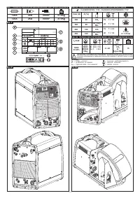
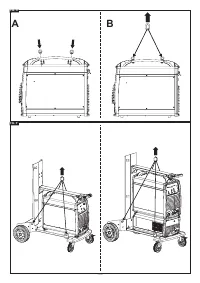
5.1 UNPACKING
- Unpack the trolley and assemble as indicated in the supplied instructions.
- Unpack the welding machine, the wire feeder, and the cooling group if present;
install on the trolley
NOTE: Insert the polarisation connector if the GRA is not connected (FIG. E)
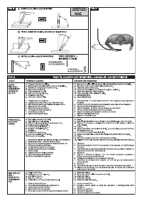
5.2 LIFTING THE WELDING MACHINE OR THE WELDING EQUIPMENT
- he welding machine must be lifted as shown in the figure
(FIG. O),
with no removable
parts that can detach (torch, gas pipes, cables, etc.).
As shown in the illustration, assemble the attachment rings using the two M8x25
screws provided.
Please note:
eyelet rings for lifting, with threaded hole M8, are not supplied.
- The welding equipment must be lifted as shown in the figure
(FIG. P)
, with no
removable parts that can detach (wire feeder, bottle, cables, remote control)
Please note:
use all 4 lifting points contemporaneously


