Сварочное оборудование Telwin INVERPULSE 425 MIG TIG MMA - инструкция пользователя по применению, эксплуатации и установке на русском языке. Мы надеемся, она поможет вам решить возникшие у вас вопросы при эксплуатации техники.
Если остались вопросы, задайте их в комментариях после инструкции.
"Загружаем инструкцию", означает, что нужно подождать пока файл загрузится и можно будет его читать онлайн. Некоторые инструкции очень большие и время их появления зависит от вашей скорости интернета.


- 6 -
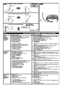
RESIDUAL RISKS
- OVERTURNING: position the welding machine on a horizontal surface that is
able to support the weight: otherwise (e.g. inclined or uneven floors etc.) there
is danger of overturning.
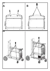
- Never lift the trolley assembled with the welding machine, wire feeder and
cooling system (when present).
- The only permitted lifting method is that described in the “INSTALLATION”
section of this manual.
- IMPROPER USE: it is hazardous to use the welding machine for any work
other than that for which it was designed (e.g. de-icing mains water pipes).
- MOVING THE WELDING MACHINE AND ITS TROLLEY: always secure the gas
bottle with appropriate equipment, to prevent it falling accidentally.
The safety guards and moving parts covers of the welding machine and of the
wire feeder should be in their proper positions before connecting the welding
machine to the power supply.
WARNING! Any manual operation carried out on the moving parts of the wire
feeder, for example:
- Replacing rollers and/or the wire guide
- Inserting wire in the rollers
- Loading the wire reel
- Cleaning the rollers, the gears and the area underneath them
- Lubricating the gears
SHOULD BE CARRIED OUT WITH THE WELDING MACHINE SWITCHED OFF
AND DISCONNECTED FROM THE POWER SUPPLY OUTLET.
2. INTRODUCTION AND GENERAL DESCRIPTION
2.1 INTRODUCTION
This welding machine consists of a power source with an integrated wire feeder.
The power source is a multi-procedure (continuous and pulsed MIG-MAG SYNERGIC,
TIG and MMA) 3-phase powered rectifier with microprocessor controlled electronic
regulation (switch-mode), with primary side whole bridge.
The wire feeder is equipped with a 4-roller motorised wire puller unit with independent
adjustment of pulling pressure; the digital control panel is integrated with the
microprocessor adjustment board and it contains fundamentally three condensed
functions:
a) PARAMETER SETTINGS AND ADJUSTMENTS
With this user interface it is possible to set and adjust the operating parameters,
select previously stored programs, view parameter status and values on the
display.
b) RECALLING PRE-STORED SYNERGIC PROGRAMS FOR MIG-MAG WELDING
These programs are pre-defined and stored by the manufacturer (so cannot be
modified); when the user recalls one of these programs, he can select a specific job
point (corresponding to a set of various independent welding parameters), adjusting
a single magnitude. This is the
SINERGY
concept, which makes it extremely easy
to achieve perfect adjustment of the welding machine depending on each specific
operating condition.
c) STORING/RECALLING CUSTOMISED PROGRAMS
This function is available when working within a synergic program and also when
in manual mode (in this case the setting for all the welding parameters is at the
discretion of the operator). This mode of operation allows the user to store and later
recall a specific welding procedure.
2.2 METAL WELDABILITY
MIG-MAG
The welding machine is suitable for MIG welding of aluminium and its
alloys, MIG brazing is typically carried out on galvanised plate and MAG welding on
carbon, low alloy and stainless steels.
MIG welding of aluminium and its alloys should be carried out using core wire with a
composition that is compatible with the material being welded and pure Ar (99.9%)
protective gas.
MIG brazing can be carried out, typically, on galvanised plate using core wire in copper
alloy (e.g. copper silicon or copper aluminium) with pure Ar (99.9%) protective gas.
MAG welding with carbon and low alloy steels should be done using core wire with a
composition that is compatible with the material to be welded and with CO
2
, or with an
Ar/CO
2
or Ar/CO
2
-O
2
mixture, as the protective gas (Argon normally > 80%).
For welding stainless steel, Ar/O
2
or Ar/CO
2
gas mixtures are normally used (Ar
normally> 98%).
TIG
The welding machine is suitable for TIG welding with direct current (DC). with
contact arc strike (LIFT ARC mode), and is suitable for use with all steels (carbon, low
and high alloys) and heavy metals (copper, nickel, titanium and their alloys) with pure
Ar (99.9%) protective gas or, for particular operations, with Argon/Helium mixtures.
MMA
The welding machine is suitable for MMA electrode welding in direct current
(DC) with all types of coated electrodes.
2.3 STANDARD ACCESSORIES
- ARGON bottle adapter
- Return cable complete with earth clamp.
- Pressure reducing valve, 2 pressure gauges.
- 1.5 m. cable connection kit
- G.R.A. water cooling system
(only for R.A. version).
- MIG torch
(the R.A. version is water cooled).
- Wire feeder
- Coil cover kit.
- Trolley
2.4 OPTIONAL ACCESSORIES
- Remote control 1 potentiometer (only TIG and MMA).
- Manual remote control, 2 potentiometers.
- Pedal remote control (only TIG and MMA).
- G.R.A water cooling system
(standard accessories only for the R.A. version).
- R.A. connecting cable kit, 4m, 10m, 30m.
- Connecting cable kit, 4 or 10 m.
- Wire feeder wheel kit.
- Aluminium welding kit
- Flux-core wire welding kit.
- MMA 600A welding kit.
- MIG torch 5m 500A.
- MIG torch 3m 500A R.A.
(standard accessory only for the R.A. version).
- MIG torch 5m 500A R.A.
- TIG torch 4 or 8m, 220A.
- TIG torch 4 or 8m 350A R.A.
- MIG/TIG UP/DOWN torch with/without potentiometer.
- PUSH PULL torch.
- Torch with serial 485.
- Double bottle kit.
3. TECHNICAL DATA
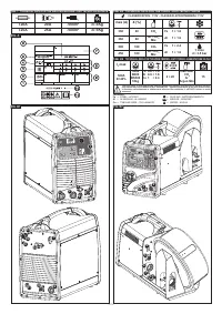
3.1 DATA PLATE (FIG. A)
The most important data regarding use and performance of the welding machine are
summarised on the rating plate and have the following meaning:
1-
Protection rating of the covering.
2-
Symbol for power supply line:
1~: single phase alternating voltage;
3~: three phase alternating voltage.
3-
Symbol
S
: indicates that welding operations may be carried out in environments
with heightened risk of electric shock (e.g. very close to large metallic volumes).
4-
Symbol for welding procedure provided.
5-
Symbol for internal structure of the welding machine.
6-
EUROPEAN standard of reference, for safety and construction of arc welding
machines.
7-
Manufacturer’s serial number for welding machine identification (indispensable for
technical assistance, requesting spare parts, discovering product origin).
8-
Performance of the welding circuit:
- U
0
:
maximum no-load voltage (open welding circuit).
- I
2
/U
2
:
current and corresponding normalised voltage that the welding machine can
supply during welding.
- X :
Duty cycle: indicates the time for which the welding machine can supply
the corresponding current (same column). It is expressed as %, based on a 10
minutes cycle (e.g. 60% = 6 minutes working, 4 minutes pause, and so on).
If the usage factors (on the plate, referring to a 40°C environment) are exceeded,
the thermal safeguard will trigger (the welding machine will remain in standby until
its temperature returns within the allowed limits).
- A/V-A/V:
shows the range of adjustment for the welding current (minimum
maximum) at the corresponding arc voltage.
9-
Technical specifications for power supply line:
- U
1
:
Alternating voltage and power supply frequency of welding machine (allowed
limit ±10%).
- I
1 max
: Maximum current absorbed by the line.
- I
1eff
:
: Effective current supplied.
10-
: Size of delayed action fuses to be used to protect the power line.
11-
Symbols referring to safety regulations, whose meaning is given in chapter 1
“General safety considerations for arc welding”.
Note: The data plate shown above is an example to give the meaning of the symbols
and numbers; the exact values of technical data for the welding machine in your
possession must be checked directly on the data plate of the welding machine itself.
3.2 OTHER TECHNICAL INFORMATION:
- WELDING MACHINE:
see table (TAB.1)
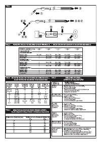
- TORCH:
see table (TAB.2A)
- WIRE FEEDER:
see table (TAB.2B)
4. WELDING MACHINE DESCRIPTION
4.1 CONTROL DEVICES, ADJUSTMENT AND CONNECTION
4.1.1 Welding machine (FIG. B1)
on front:
1- Control panel (see description).
2- Negative (-) quick connector for welding current cable (earth cable for MIG and
MMA, torch cable for TIG).
3- Gas connector for TIG torch.
4- 3p connector for TIG TORCH control cable
5- 14p connector for remote control connection (optional).
6- Positive (+) quick connector for TIG welding earth cable.
at the back:
7- Main ON/OFF switch.
8- Gas pipe connector (bottle) for TIG welding.
9- Positive (+) quick connector for connecting the welding current cable to the wire
feeder.
10- 14p connector for wire feeder control cable.
11- Power supply cable with cable gland.
12- 5p connector for water cooling system.
13- Fuse.
14- USB socket.
4.1.2 Wire feeder (FIG. B2)
on front:
1- Control panel (see description).
2- 14p connector for remote control connection.
3- Quick connectors for MIG torch water pipes.
4- Centralised connection for MIG torch (Euro).
at the back:
5- 14p connector for control cable connection with the welding machine.
6- Positive (+) quick connector for connecting the welding current cable to the
welding machine.
7- Gas pipe connector (bottle) for MIG welding.
8- Quick connectors for connecting the cooling water delivery and return pipes.
9- Fuse.
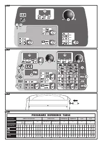
4.2 WELDING MACHINE CONTROL PANEL (FIG. C)
The control panel is enabled (i.e. the commands and signals are active) only if the
welding machine is not connected to the wire feeder, or if the MMA or TIG process is
set. Should the welding machine be connected to the wire feeder, or the function set
is MIG, the latter automatically takes complete control and the word “feed” appears on
the welding machine display (3).
1- LED indicating ALARM
(machine output is disabled). An alarm message
appears on the display (3).
The welding machine is reset automatically when the cause for alarm has been


