
Генераторы Telwin THUNDER 220 AC HONDA 825001 - инструкция пользователя по применению, эксплуатации и установке на русском языке. Мы надеемся, она поможет вам решить возникшие у вас вопросы при эксплуатации техники.
Если остались вопросы, задайте их в комментариях после инструкции.
"Загружаем инструкцию", означает, что нужно подождать пока файл загрузится и можно будет его читать онлайн. Некоторые инструкции очень большие и время их появления зависит от вашей скорости интернета.
- 7 -
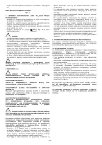
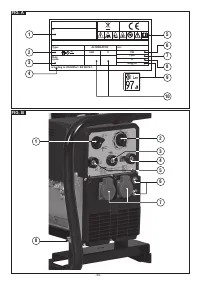
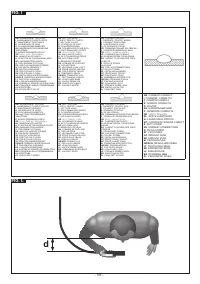
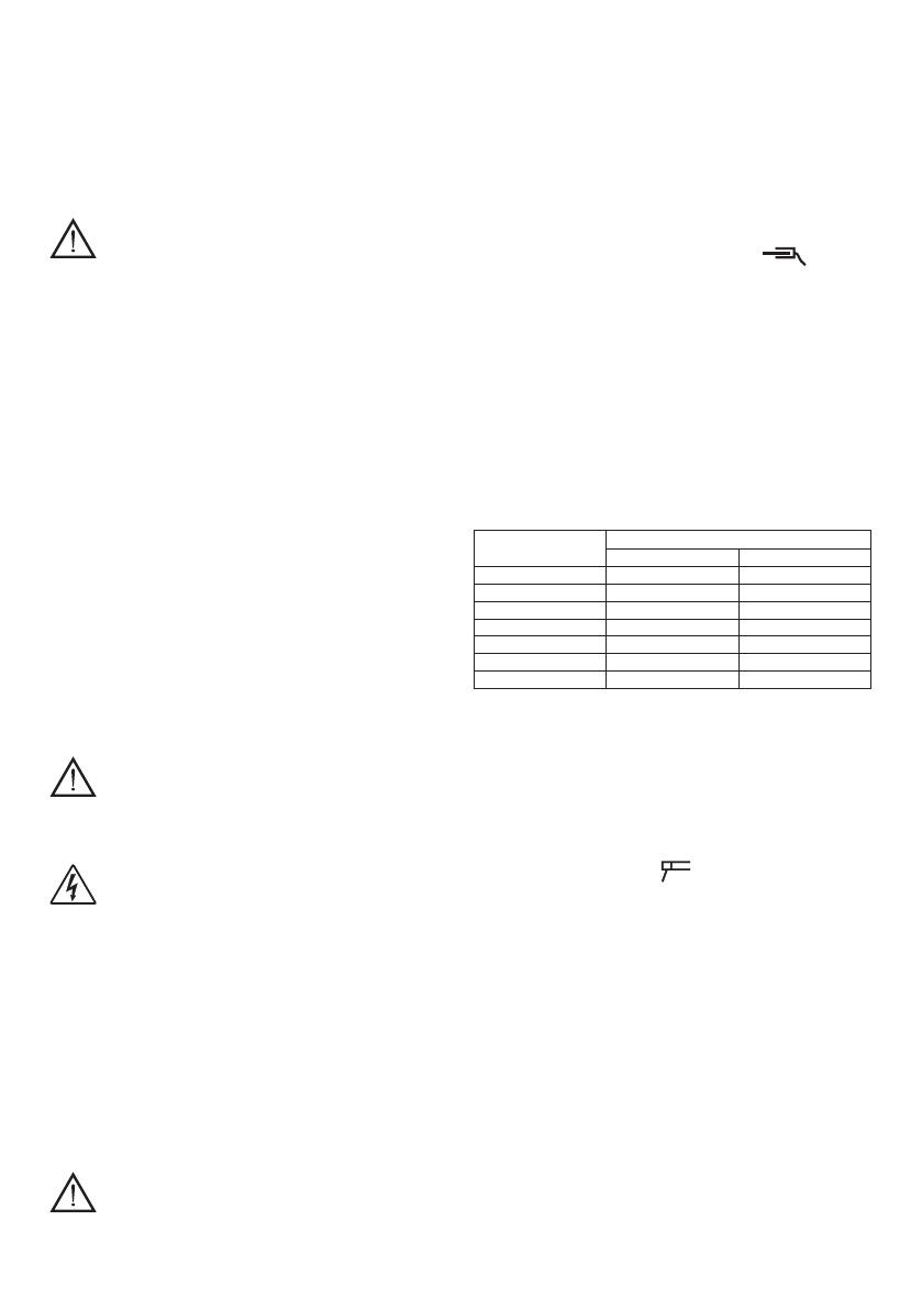
2- Selector for adjusting the 3 welding ranges and for adjusting the
output voltage of the auxiliary sockets.
3- Negative quick connector (-) for welding cable connection.
4- Positive quick connector (+) for welding cable connection.
5- Auxiliary socket voltmeter.
6- Circuit-breaker.
7- Single-phase socket.
8- Three-phase socket.
9- Hole for earth connection.
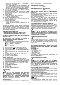
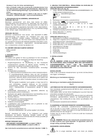
5. INSTALLATION
WARNING! CARRY OUT ALL INSTALLATION AND
ELECTRIC CONNECTION OPERATIONS WITH THE ENGINE-
DRIVEN WELDING MACHINE RIGOROUSLY SWITCHED OFF.
THE ELECTRIC CONNECTIONS MUST ONLY BE CARRIED OUT
BY EXPERT OR QUALIFIED TECHNICIANS.
PREPARATION
Unpack the engine-driven welding machine and assemble the
separate parts included in the package.
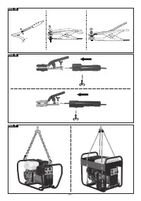
Return cable-clamp assembly
Fig. D
Electrode-holder clamp-welding cable assembly
Fig. E
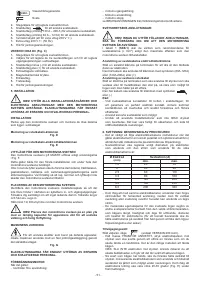
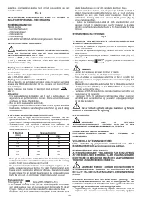
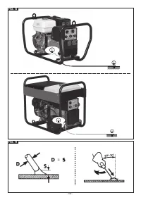
HOW TO LIFT THE ENGINE-DRIVEN WELDING MACHINE
The engine-driven welding machine MUST be lifted as shown in Fig.
F.
This is valid for both initial installation and for the entire life of the
engine-driven welding machine.
Note: The wire feeder, gas bottle, cables and interconnecting and
supply cables must be removed before lifting the engine-driven
welding machine. Make sure the lifting cables, belts or chains do not
damage the engine-driven welding machine accessory parts.
POSITIONING THE ENGINE-DRIVEN WELDING MACHINE
Make sure the engine-driven welding machine is positioned in a
place where the cooling air inlets and outlets cannot be obstructed;
at the same time make sure that conductive dust, corrosive vapours,
humidity etc. cannot be drawn into the machine.
Leave at least 1m of free space all around the engine-driven welding
machine.
WARNING! Position the engine-driven welding machine
on a level surface with sufficient load-bearing capacity, so that it
cannot topple or shift dangerously.
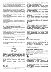
MACHINE EARTHING
To prevent electric shocks caused by faulty user equipment,
the machine must be connected using a fixed earthing system and
through the relative terminal.
Fig. G
THE ELECTRIC CONNECTIONS MUST ONLY BE CARRIED OUT
BY EXPERT OR QUALIFIED TECHNICIANS.
INTERNAL COMBUSTION ENGINE
Regarding:
- checks before use;
- engine starting;
- engine use;
- engine stopping;
refer to the USER MANUAL of the internal combustion engine
producer.
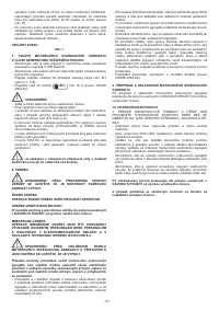
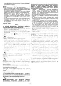
WELDING CIRCUIT CONNECTIONS
WARNING! BEFORE CARRYING OUT THE FOLLOWING
CONNECTIONS MAKE SURE THE ENGINE-DRIVEN WELDING
MACHINE IS SWITCHED OFF.
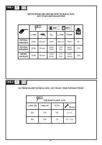
The Table
(TAB. 1)
shows the recommended sizes of the welding
cables (in mm2), according to the maximum current output from the
engine-driven welding machine.
Electrode holder clamp-welding cable connection
There is a special clamp on the terminal that tightens the uncovered
part of the electrode.
Connect this cable to the clamp with the symbol (60A-120A) or
(130A-200A) or (+).
Connecting the welding current return cable
There is a special clamp on the terminal that must be connected to
the workpiece or to the metal bench on which is it positioned, and as
close as possible to the joint being worked.
Connect this cable to the clamp with the symbol
or (-).
Recommendations:
- Screw the welding cable connectors right down into the quick
couplings, so as to ensure perfect electrical contact; otherwise, the
connectors will overheat, wear rapidly and become inefficient.
- Use welding cables that are as short as possible.
- Do not use metal structures that are not part of the workpiece to
substitute the welding current return cable; this could be dangerous
and produce an unsatisfactory weld.
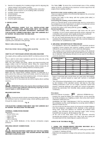
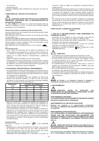
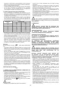
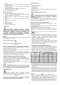
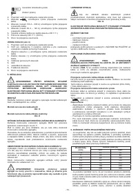
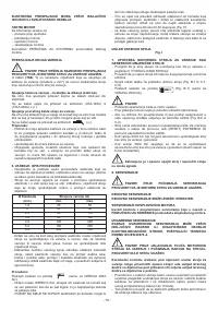
6. WELDING: DESCRIPTION OF PROCEDURE
- It is essential to refer to the indications of the electrode producer
regarding correct polarity and optimum welding currents (these
indications are generally given on the electrode packaging).
- The welding current should be adjusted according to the diameter
of the electrode used and the type of joint that is to be carried out;
as an indication the following currents can be used for the different
electrode diameters:
Ø Electrode
(mm)
Welding current (A)
min.
max.
1.6
25
50
2
40
80
2.5
60
110
3.2
80
160
4.0
120
200
5.0
160
230
6.0
200
330
- Keep in mind that high current levels are used when flat welding,
while lower currents should be used with vertical or overhead
welding.
- The mechanical characteristics of the welded joint are determined
by the intensity of the selected current, and also by the other
welding parameters such as arc length, execution speed and
position, electrode diameter and quality (for correct conservation
protect the electrodes from humidity using suitable packages or
containers).
Procedure:
Move the selector to position
(200A AC VERSION only).
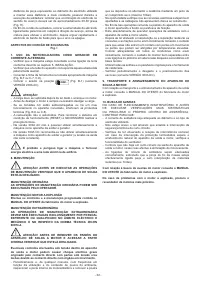
- Keeping the mask IN FRONT OF YOUR FACE, rub the electrode
tip on the workpiece as if lighting a match; this is the most correct
method for striking the arc.
WARNING: DO NOT CONTINUALLY TAP the electrode against
the workpiece as this could damage the covering, which makes it
difficult to strike the arc.
- As soon as the arc has been struck, try to keep at a certain distance
from the workpiece, equivalent to the diameter of the electrode
being used. Keep this distance as constant as possible while
welding, and remember that the electrode angle, when moving
forward must, be approx. 20-30 degrees (Fig. H).
- At the end of the weld seam, move the electrode extremity
backwards and position it above the crater to fill; then quickly lift
the electrode from the melted liquid to switch off the arc.
ASPECTS OF THE WELD SEAM
Fig. I
7. USING THE ENGINE-DRIVEN WELDING MACHINE AS A
GENERATOR IN ALTERNATE CURRENT
- Make sure the machine is connected to an earth peg as described
in chapter 5. INSTALLATION.
- Make sure the equipment voltage is the same as the auxiliary outlet
output.


