
Генераторы Telwin THUNDER 220 AC HONDA 825001 - инструкция пользователя по применению, эксплуатации и установке на русском языке. Мы надеемся, она поможет вам решить возникшие у вас вопросы при эксплуатации техники.
Если остались вопросы, задайте их в комментариях после инструкции.
"Загружаем инструкцию", означает, что нужно подождать пока файл загрузится и можно будет его читать онлайн. Некоторые инструкции очень большие и время их появления зависит от вашей скорости интернета.
- 6 -
- Fix the two welding cables as close to each other as possible.
- Operators must keep their heads and trunks as far away as
possible from the welding circuit.
- Operators must never wind the welding cables around their
body.
- Operators must never keep their body in the centre of the
welding circuit while they weld. Operators must keep both
cables on the same side of their body.
- Connect the welding current return cable to the piece to be
welded, as close as possible to the join being made/welding
spot.
- Never weld while remaining close to, sitting on or leaning
against the engine-driven welding machine (minimum
distance: 50 cm).
- Do not leave ferromagnetic objects near the welding circuit.
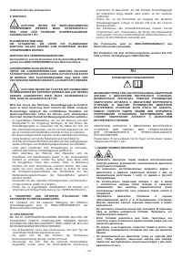
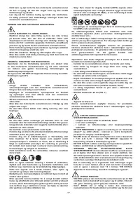
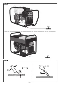
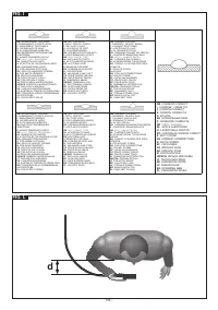
- Minimum distance d = 20 cm (Fig. L)
- Class A equipment:
This engine-driven welding machine satisfies the requirements
of the product technical standards for exclusive use in industrial
environments for professional purposes.
ADDITIONAL PRECAUTIONS
- WELDING OPERATIONS:
- In environments with increased risk of electric shock;
- In confined spaces;
- In the presence of inflammable or explosive material;
MUST ALWAYS be evaluated in advance by an “Expert
supervisor” and must always be carried out in the presence
of other people trained in emergency procedures.
The technical protection means described in sections 7.10;
A.8; A.10. of “Part 9: Installation and use” of the “EN 60974-9:
Apparatus for arc welding” Directive MUST ALWAYS be used.
- Welding should NEVER be allowed if the operator is above
floor level, unless a safety platform is used.
- VOLTAGE BETWEEN THE ELECTRODE HOLDERS OR
TORCHES: when working with more than one welding
machine on a single piece, or on several pieces that are
connected electrically, dangerous no-load voltages may build
up between two different electrode holders or torches and
may reach double the allowed limit.
It is essential for an expert coordinator to use measuring
instruments to determine whether there is a risk, and to
be able to adopt adequate safety measures as indicated
in section 7.9 of the EN 60974-9: Apparatus for arc welding
Directive. Part 9: Installation and use”.
RESIDUAL RISKS
- TOPPLING: position the engine-driven welding machine on a
horizontal surface that is suitable for supporting the weight;
if the surface is not horizontal (e.g. sloped or broken flooring,
etc...) the welding machine can topple.
- IMPROPER USE: it is dangerous to use the engine-driven
welding machine for any purpose other than that for which it
is intended (e.g. defrosting piping from the water system).
- It is forbidden to lift the engine-driven welding machine unless
the gas bottles, wire feeder and all the interconnecting or
power cables/piping (if present) have been removed.
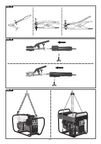
The only permitted way to lift the machine is described in the
“INSTALLATION” section of this handbook.
2. INTRODUCTION AND GENERAL DESCRIPTION
200A AC VERSION
Petrol engine-driven welding machine for MMA electrode welding in
(AC) alternate current. Electrodes: rutile. It can be used as a single-
phase AC current generator for powering all types of electric tool
(e.g. sanders, drills, dowel hole drills, demolishers, etc.) and electric
devices (e.g. lights, saws, compressors, etc.).
300A DC VERSION
Petrol or diesel engine-driven welding machine for MMA electrode
welding in (DC) direct current. It can be used with many different
electrodes: rutile, basic, cellulose, stainless, aluminium, cast iron,
etc. It can be used as a single-phase and three-phase AC current
generator for powering all types of electric tool (e.g. sanders,
drills, dowel hole drills, demolishers, etc.) , compressors, neon and
incandescent lighting systems, etc.
ACCESSORIES SUPPLIED ON REQUEST:
- MMA welding kit
- Wheel kit.
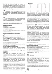
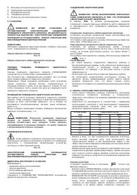
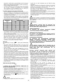
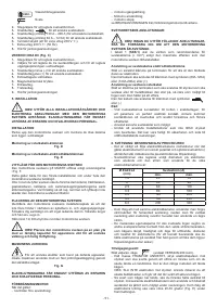
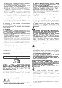
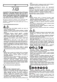
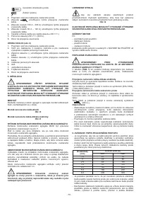
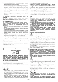
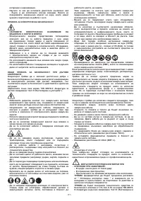
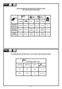
3. TECHNICAL DATA
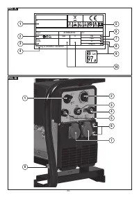
DATA PLATE
The main data regarding engine-driven welding machine performance
and use are given briefly in the characteristics plate with the following
meaning:
Fig. A
1- Serial number for engine-driven welding machine identification
(essential for servicing, requesting spare parts, searching for
product origin).
2- Symbol representing the internal structure of the engine-driven
welding machine.
3- Welding circuit performance:
- I
2
: Currents that can be supplied by the welding machine
during welding.
- X : Intermittence ratio: indicates the time during which the
engine-driven welding machine can supply the corresponding
current (same column). Expressed in %, on the basis of a
10-minute cycle (e.g. 60% = 6 minutes work, 4 minutes rest;
and so on).
If the use factors (referred to a room temperature of 40°C)
are exceeded, the thermostatic safeguard cuts in (the
engine-driven welding machine remains in stand-by until its
temperature returns within the permitted limits).
4- EUROPEAN Standard of reference for safety and for the
construction of arc welding machines.
5- Symbols that refer to safety regulations, the meanings of which
are given in chapter 1 “General safety regulations”.
6- Nominal frequency.
7- Internal combustion engine characteristic data:
- n : Rated load speed.
8- Casing protection grade.
9- Sound power (or pressure) level guaranteed by the engine-
driven welding machine.
10- Auxiliary power output:
- Nominal output voltage (V).
- Nominal output power 1ph (single-phase) and/or 3ph (three-
phase).
Note: The meaning of the symbols and figures given in the example
plate shown are indicative; the exact values of the technical data
of the engine-driven welding machine in your possession must be
looked for directly on the plate of the machine itself.
OTHER TECHNICAL INFORMATION:
- ENGINE-DRIVEN WELDING MACHINE: see table 1 (TAB.1)
- ELECTRIC HOLDER CLAMP: see table 2 (TAB.2)
The weight of the engine-driven welding machine is given in
table 1 (TAB.1)
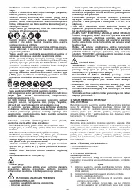
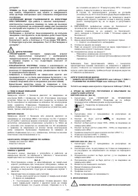
4. ENGINE-DRIVEN WELDING MACHINE CONTROL DEVICES,
ADJUSTMENT AND CONNECTION
200A DC VERSION (Fig. B)
1- ALTERNATE CURRENT-WELDING MACHINE GENERATOR
selector. Use to select the operation mode to be used:
230V 1~
Alternate current generator.
Welding machine.
2- Selector switch for adjusting the welding current.
3- Quick connector
for welding cable connection.
4- Quick connector (range 130A – 200A) for welding cable
connection
5- Quick connector (range 60A – 120A) for welding cable connection
6- Thermostatic safeguard (one for each 230V 1~ connector).
7- Auxiliary connectors 230V 1~ (50Hz).
8- Hole for earth connection.
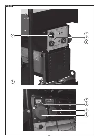
300A DC VERSION (Fig. C)
1- Selector switch for adjusting the welding current


