
Пилы торцовочные Bosch 0.601.B29.021 - инструкция пользователя по применению, эксплуатации и установке на русском языке. Мы надеемся, она поможет вам решить возникшие у вас вопросы при эксплуатации техники.
Если остались вопросы, задайте их в комментариях после инструкции.
"Загружаем инструкцию", означает, что нужно подождать пока файл загрузится и можно будет его читать онлайн. Некоторые инструкции очень большие и время их появления зависит от вашей скорости интернета.


English |
23
Bosch Power Tools
1 609 92A 3A2 | (1.9.16)
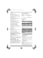
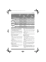
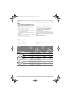
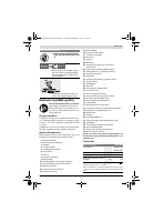
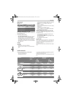
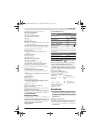
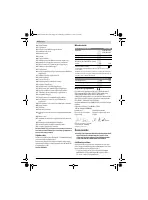
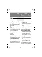
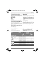
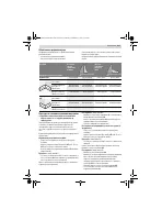
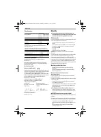
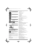
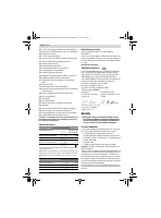
Technical Data
Declaration of Conformity
We declare under our sole responsibility that the product de-
scribed under “Technical Data” is in conformity with all rele-
vant provisions of the directives 2011/65/EU, until
19 April 2016: 2004/108/EC, from 20 April 2016 on:
2014/30/EU, 2006/42/EC including their amendments and
complies with the following standards: EN 61029-1,
EN 61029-2-9, EN 50581.
Technical file (2006/42/EC) at:
Robert Bosch Power Tools GmbH, PT/ECS,
70538 Stuttgart, GERMANY
Robert Bosch Power Tools GmbH
70538 Stuttgart, GERMANY
Stuttgart, 01.01.2017
Assembly
Avoid unintentional starting of the machine. During as-
sembly and for all work on the machine, the power plug
must not be connected to the mains supply.
Delivery Scope
Before starting the operation of the machine for the first time,
check if all parts listed below have been supplied:
– Mitre saw with mounted saw blade
– Tilt-protector bar
24
with fastening set
35
(2 bolts, 2
washers, 2 square nuts)
– Dust bag
19
– Material clamp
18
– Hex key/cross-head screwdriver
22
Note:
Check the power tool for possible damage.
Before further use of the machine, check that all protective
devices are fully functional. Any lightly damaged parts must
be carefully checked to ensure flawless operation of the tool.
All parts must be properly mounted and all conditions fulfilled
that ensure faultless operation.
Damaged protective devices and parts must be immediately
replaced by an authorised service centre.
Mounting Individual Components
– Carefully remove all parts provided from their packaging.
Remove all packing material from the power tool and the
accessories provided.
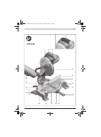
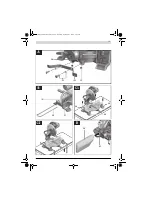
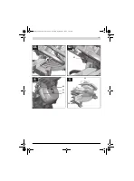
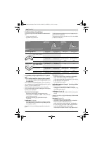
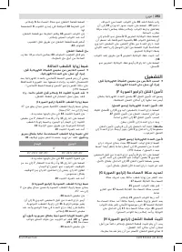
Mounting the Tilt-Protector Bar (see figure A)
Before using the power tool for the first time, the tilt-protec-
tor bar
24
must be mounted.
Use the “tilt-protector bar” fastening set
35
for mounting.
– Insert the square nuts
35
into the intended holes
34
in the
base plate.
– Place the washers
35
on the fastening bolts
35
and use
them to screw the tilt-protector bar
24
into the inserted
nuts.
Never remove the tilt-protector bar.
Without the use of
the tilt-protector bar, the machine does not stand safely
and can tip over, especially when sawing at maximum mi-
tre/bevel angles.
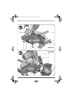
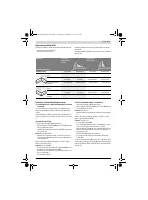
Mounting the Extension Bars (see figure B)
Long workpieces must be underlaid or supported at their free
end.
To extend the saw table additionally, extension bars can be
mounted both to the left or right of the power tool.
– Insert the extension bars
36
on both sides of the power
tool to the stop in the drill holes
16
intended for this pur-
pose.
– Tighten the fastening bolts
37
to secure the extension bars.
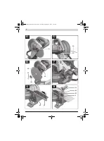
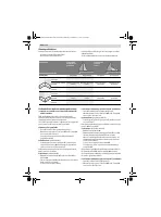
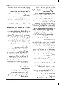
Stationary or Flexible Mounting
To ensure safe handling, the machine must be mounted
on a level and stable surface (e. g., workbench) prior to
using.
Mounting to a Working Surface (see figures C1 – C2)
– Fasten the power tool with suitable screw fasteners to the
working surface. The mounting holes
14
serve for this pur-
pose.
or
– Clamp the power tool with commercially available screw
clamps by the feet to the working surface.
Mounting to a Bosch Saw Stand
With the height-adjustable legs, Bosch GTA saw stands pro-
vide firm support for the power tool on any surface. The work-
piece supports of the saw stand are used for underlaying long
workpieces.
Read all safety warnings and instructions included with
the worktable.
Failure to observe safety warnings and in-
structions can lead to electrical shock, fire and/or cause
serious injuries.
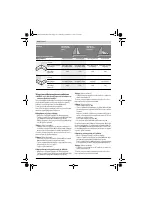
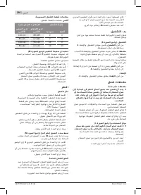
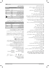
Mitre Saw
GCM 10 MX
Article number
3 601 M29 02.
3 601 M29 0P.
Rated power input
W
1700
No-load speed
min
-1
4800
Weight according to
EPTA-Procedure 01:2014
kg
16.8
Protection class
/
II
Permissible workpiece dimensions (maximum/minimum) see page 26.
The values given are valid for a nominal voltage [U] of 230 V. For differ-
ent voltages and models for specific countries, these values can vary.
Dimension of suitable saw blades
Saw blade diameter
mm
254
Blade body thickness
mm
1.8 – 2.8
Mounting hole diameter
mm
30
Henk Becker
Executive Vice President
Engineering
Helmut Heinzelmann
Head of Product Certification
PT/ECS
OBJ_BUCH-2583-003.book Page 23 Thursday, September 1, 2016 7:50 AM
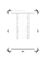
Содержание
- 174 Безопасность людей
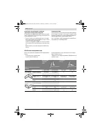
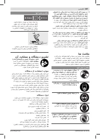
- 175 Не становитесь на электроинструмент.; Символы; Символы и их значение
- 176 Описание продукта и услуг; Применение по назначению
- 177 Технические данные; Применяйте средства защиты органов слуха!; Заявление о соответствии; Сборка; Комплект поставки; Торцовочно-усовочная пила; Размеры пильных дисков
- 178 Стационарный или временный монтаж; Монтаж на верстаке производства Bosch; Отсос пыли и стружки; Избегайте скопления пыли на рабочем месте.
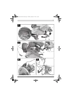
- 179 Демонтаж пильного диска; Работа с инструментом; Снятие крепления детали; Настройка угла распила
- 180 Включение электроинструмента
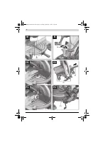
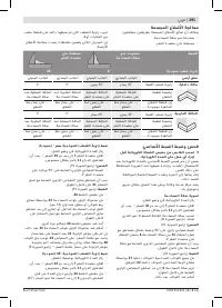
- 181 Специальные заготовки; Обработка профильных реек; Настройка упорной планки
- 182 Настройка угла наклона в 0 °; Техобслуживание и сервис; Техобслуживание и очистка; Очистка; Принадлежности; Товарный No
- 183 Россия; Беларусь; Утилизация
Характеристики

Остались вопросы?Не нашли свой ответ в руководстве или возникли другие проблемы? Задайте свой вопрос в форме ниже с подробным описанием вашей ситуации, чтобы другие люди и специалисты смогли дать на него ответ. Если вы знаете как решить проблему другого человека, пожалуйста, подскажите ему :)


