Коммутаторы NETGEAR S3300-28X (GS728TX) 24x1GE - инструкция пользователя по применению, эксплуатации и установке на русском языке. Мы надеемся, она поможет вам решить возникшие у вас вопросы при эксплуатации техники.
Если остались вопросы, задайте их в комментариях после инструкции.
"Загружаем инструкцию", означает, что нужно подождать пока файл загрузится и можно будет его читать онлайн. Некоторые инструкции очень большие и время их появления зависит от вашей скорости интернета.


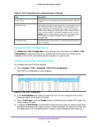


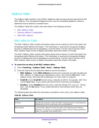
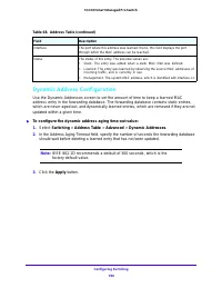
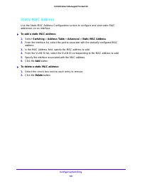
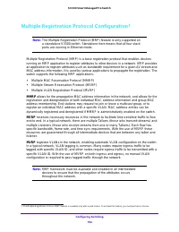


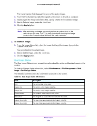
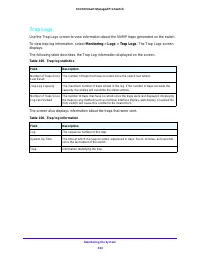


Maintenance
308
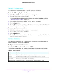
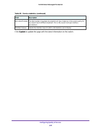
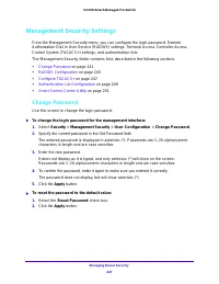
S3300 Smart Managed Pro Switch
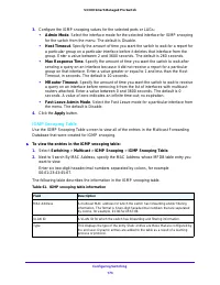
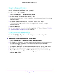
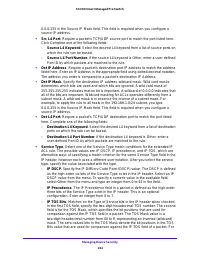
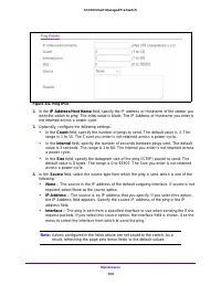
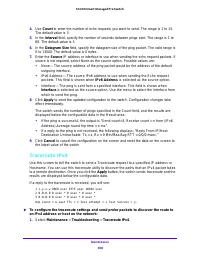
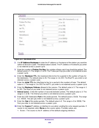
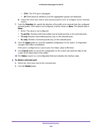
4.
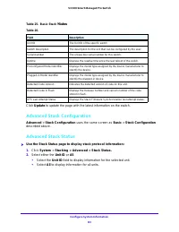
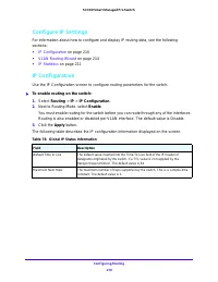
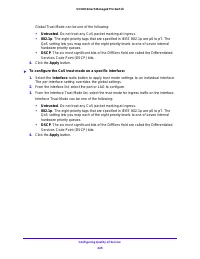
Use
Count
to enter the number of echo requests you want to send. The range is 1 to 15.
The default value is 3.
5.
In the
Interval
field, specify the number of seconds between pings sent. The range is 1 to
60. The default value is 3.
6.
In the
Datagram Size
field, specify the datagram size of the ping packet. The valid range is
0 to 13000. The default value is 0 bytes.
7.
Enter the
Source
IP address or interface to use when sending the echo request packets. If
source is not required, select None as the source option. Possible values are:
•
None — The source address of the ping packet would be the address of the default
outgoing interface.
•
IPv6 Address — The source IPv6 address to use when sending the Echo request
packets. This field is shown when
IPv6 Address
is selected as the source option.
•
Interface — The ping is sent from a specified interface. This field is shown when
Interface
is selected as the source option. Use the menu to select the interface from
which to send the ping.
8.
Click
Apply
to send the updated configuration to the switch. Configuration changes take
effect immediately.
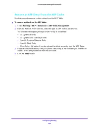
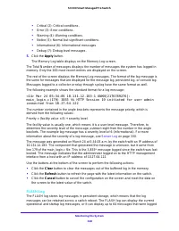
The switch sends the number of pings specified in the Count field, and the results are
displayed below the configurable data in the Result area:
•
If the ping is successful, the output is “Send count=3, Receive count =
n
from (IPv6
Address).Average round trip time =
n
ms”.
•
If a reply to the ping is not received, the following displays: “Reply From IP/Host:
Destination Unreachable. Tx = x, Rx = 0 Min/Max/Avg RTT = 0/0/0 msec.”
9.
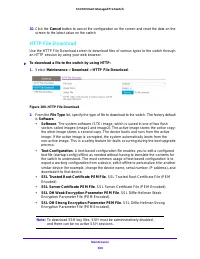
Click
Cancel
to cancel the configuration on the screen and reset the data on the screen to
the latest value of the switch.
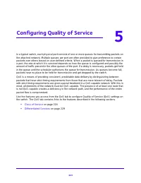
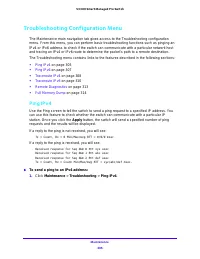
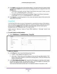
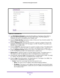
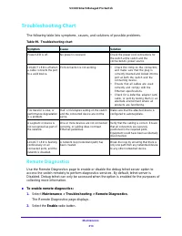
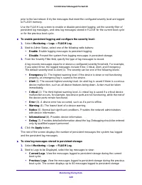
Traceroute IPv4
Use this screen to tell the switch to send a Traceroute request to a specified IP address or
Hostname. You can use this traceroute utility to discover the paths that an IPv4 packet takes
to a remote destination. Once you click the
Apply
button, the switch sends traceroute and the
results are displayed below the configurable data.
If a reply to the traceroute is received, you will see:
1 x.y.z.w 9869 usec 9775 usec 10584 usec
2 0.0.0.0 0 usec * 0 usec * 0 usec *
3 0.0.0.0 0 usec * 0 usec * 0 usec *
Hop Count = w Last TTL = z Test attempt = x Test Success = y.
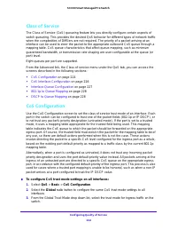
To configure the traceroute settings and send probe packets to discover the route to
an IPv4 address or host on the network:
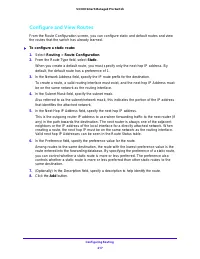
1.
Select
Maintenance
>
Troubleshooting
>
Traceroute IPv4
.
Характеристики

Остались вопросы?Не нашли свой ответ в руководстве или возникли другие проблемы? Задайте свой вопрос в форме ниже с подробным описанием вашей ситуации, чтобы другие люди и специалисты смогли дать на него ответ. Если вы знаете как решить проблему другого человека, пожалуйста, подскажите ему :)
