
Генераторы Telwin MOTOINVERTER 264D CE LOMBARDINI 815980 - инструкция пользователя по применению, эксплуатации и установке на русском языке. Мы надеемся, она поможет вам решить возникшие у вас вопросы при эксплуатации техники.
Если остались вопросы, задайте их в комментариях после инструкции.
"Загружаем инструкцию", означает, что нужно подождать пока файл загрузится и можно будет его читать онлайн. Некоторые инструкции очень большие и время их появления зависит от вашей скорости интернета.

ELECTRICAL CONNECTIONS MUST BE MADE WITH THE
- Slowly pull the handgrip until a strong resistance is felt.
- Slowly follow the handgrip of the cord into the starting position .
ENGINE-DRIVEN WELDER SWITCHED OFF COMPLETELY THE
- Pull the handgrip to the end with a definite and uniform movement.
ELECTRICAL CONNECTIONS MUST BE MADE ONLY AND
- Slowly follow the starting cord handgrip into the initial position.
EXCLUSIVELY BY EXPERT OR SKILLED PERSONNEL.
________________________________________________________________________________
- After a few seconds rotate the accelerator lever to the MAX
(Fig. I)
SETTING UP THE ENGINE-DRIVEN WELDER
Shutoff (manual)
Unpack the engine-driven welder and assemble the separate parts
- Before shutoff, rotate the accelerator lever to the MIN for a few
contained in the package.
seconds.
- Push the STOP lever as in F
ig. M
.
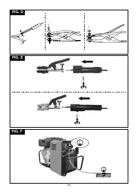
Assembling the clamp-return cable
Fig. D
CONNECTIONS FOR THE WELDING CIRCUIT
________________________________________________________________________________
Assembling the electrode-holder clamp-welding cable
Fig. E
WARNING!
BEFORE
MAKING
THE
FOLLOWING
CONNECTIONS MAKE SURE THE ENGINE-DRIVEN WELDER IS
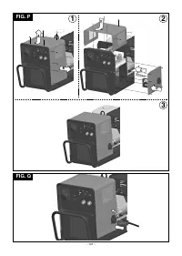
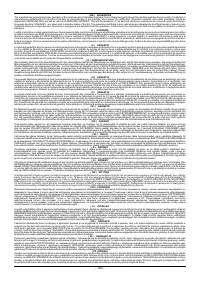
HOW TO LIFT THE MACHINE
SWITCHED OFF.
The machine should be lifted as shown in
Fig. S
. This holds for both
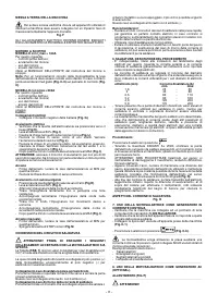
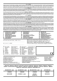
The table
(TAB. 1)
shows the recommended values for the welding
2
initial installation and for the entire life of the machine.
cables (in mm ) based on the maximum current supplied by the
engine-driven welder.
________________________________________________________________________________
POSITIONING THE ENGINE-DRIVEN WELDER
Almost all coated electrodes should be connected to the positive
Choose a position to install the engine-driven welder so that there are
terminal (+) of the engine-driven welder; exceptionally, connection is
no obstructions to the cooling air inlets and outlets; at the same time
to the negative terminal (-) for acid coated electrodes.
make sure there is no intake of conductive powders, corrosive
vapours, humidity etc.
Connecting the electrode-holder-clamp welding cable
Keep at least 1m free space all around the engine-driven welder.
On the terminal attach a special clamp to close the exposed part of the
______________________________________________
electrode.
This cable should be connected to the terminal with the symbol (
+
)
WARNING! Position the engine-driven welder on a flat
surface that will support its weight so that it cannot tipp or shift
Connecting the welding current return cable
dangerously.
On the terminal attach a clamp that should be connected to the piece
being welded or to the metal bench on which it is placed, as close as
______________________________________________
possible to the join being made.
This cable should be connected to the terminal with the symbol (
-
)
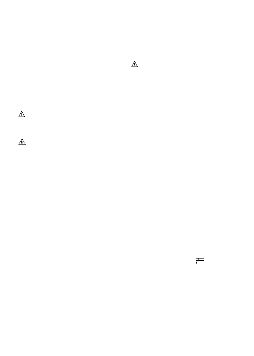
EARTHING THE MACHINE
________________________________________________________________________________
Advice:
- Screw the welding cable connectors right into the quick connections,
To prevent electric shock from faulty user apparatus the
to ensure a perfect electrical contact; otherwise an imperfect contact
machine must be connected to a fixed earth installation using the
will cause overheating in the connectors and they will quickly
terminal supplied for this purpose.
become damaged and inefficient.
Fig. F
- The welding cables used should be as short as possible.
- Do not use metal structures that are not part of the piece being
ELECTRICAL CONNECTIONS MUST BE CARRIED OUT ONLY
welded, to replace the welding current return cable; this could be a
AND EXCLUSIVELY BY EXPERT OR SKILLED PERSONNEL.
safety hazard and give an unsatisfactory result for the weld.
________________________________________________________________________________
6. WELDING: DESCRIPTION OF THE PROCEDURE
ENGINE
- It is essential to follow the electrode manufacturer's instructions as
MODEL with I max = 160A
2
regards the correct polarity and optimal welding current (these
As regards:
instructions are usually printed on the package containing the
- checks before use;
electrodes).
- starting the engine;
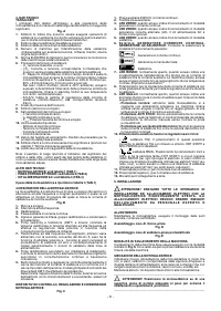
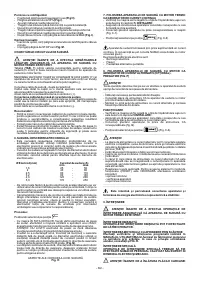
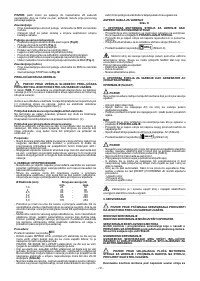
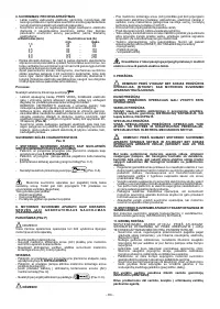
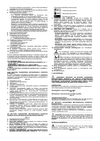
- The welding current should be adjusted according to the diameter of
- using the engine;
the electrode being used and the type of join to be made; indicatively,
- stopping the engine;
the currents used for the different electrode diameters are:
refer to the USER'S HANDBOOK supplied by the engine
ø Electrode (mm)
Welding current (A)
manufacturer.
min.
max.
Note:
For a correct operation of the engine-driven welder, turn the
1,6
25
-
50
lever of the accelerator to the right.
2
40
-
80
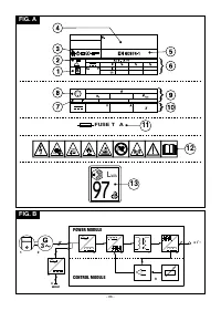
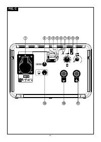
Otherwise, the yellow led
(Fig. C-9)
on the control panel
(Fig. C)
may
2,5
60
-
110
turn on.
3,2
80
-
160
4,0
120
-
200
MODEL with I max = 200A
2
5,0
170
-
250
As regards:
- Bear in mind that for the same electrode diameter high current
- checks before use;
values will be used for horizontal welding, while lower values should
- starting the engine;
be used for vertical or overhead welding.
- using the engine;
- As well as being determined by the chosen current intensity, the
- stopping the engine;
mechanical properties of the welded join are also determined by
refer to the USER'S HANDBOOK supplied by the engine
other welding parameters such as arc length, working speed and
manufacturer.
position, electrode diameter and quality (to store the electrodes
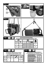
Furthermore:
correctly keep them in a dry place in their original package or in
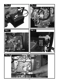
Electrical connections
suitable containers).
- Connect the negative terminal of the batteries
(Fig. G)
.
Procedure:
Electrical start
- Check that the lever of the electrovalve is positioned downwards
Position the selector to the correct position
(Fig H)
.
- Keeping the mask IN FRONT OF THE FACE, scratch the tip of the
- The accelerator lever is at 50%
(Fig. I)
.
electrode along the piece to be welded as though you were striking a
- Fit the key into the motor starting panel
(Fig. L)
.
match; this is the most correct way to strike the arc.
- Rotate the key clockwise by one step. Check that the red leds 2 and
WARNING: DO NOT TAP the electrode on the piece; this could
3 turn on
(Fig. L)
.
damage the coating, making it difficult to strike the arc.
- Rotate the key by a further step. Once the starting is done, release
- As soon as the arc has struck, try to keep at a distance from the
the key. Check that the green led 1 turns on and leds 2 and 3 turn off
piece equivalent to the diameter of the electrode in use and keep this
(Fig. L)
.
distance as constant as possible while carrying out the weld;
- After a few minutes, rotate the accelerator lever to the MAX
(Fig. I)
.
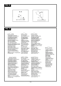
remember that the electrode should be inclined at about 20-30
WARNING:
operate the starting motor for not more that 20
degrees in the direction of progress
(Fig. N)
.
consecutive seconds. If the motor does not start wait for a further
- At the end of the weld seam take the electrode slightly backwards
minute before repeating the starting operation.
with respect to the direction of progress, above the crater so that it is
filled, then lift the electrode quickly from the weld pool so that the arc
Shutoff
is extinguished.
- Before shutoff, rotate the accelerator lever to the MIN for a few
minutes.
APPEARANCE OF THE WELD SEAM
- Rotate the key by one step anti-clockwise.
Fig. O
Starting by recoil
7. USING THE ENGINE-DRIVEN WELDER AS A DIRECT
- Position the electrovalve lever upwards
(Fig H)
.
CURRENT GENERATOR
- Accelerator lever to 50%
(Fig. I)
.
- Make sure the machine is connected to an earth stake as described
- Hold the handgrip of the starting cord.
- 5 -


