
Генераторы Telwin MOTOINVERTER 264D CE LOMBARDINI 815980 - инструкция пользователя по применению, эксплуатации и установке на русском языке. Мы надеемся, она поможет вам решить возникшие у вас вопросы при эксплуатации техники.
Если остались вопросы, задайте их в комментариях после инструкции.
"Загружаем инструкцию", означает, что нужно подождать пока файл загрузится и можно будет его читать онлайн. Некоторые инструкции очень большие и время их появления зависит от вашей скорости интернета.

An expert coordinator must use measuring instruments to
(TAB.1)
determine whether a risk exists and should take suitable
protective measures as indicated in section 5.9 of the "IEC
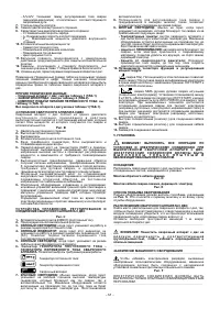
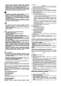
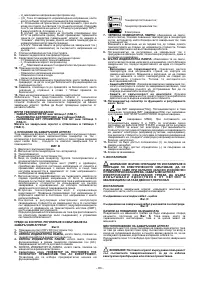
4. DESCRIPTION OF THE ENGINE-DRIVEN WELDER
TECHNICAL SPECIFICATION or CLC/TS 62081".
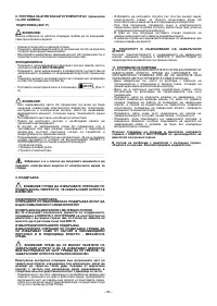
The engine-driven welder consists of an engine that drives a
permanent magnet high frequency alternator which is used to supply
power to a power module from which the welding current and auxiliary
RESIDUAL RISKS
current are taken.
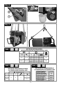
Fig. B
- IMPROPER USE: it is dangerous to use the engine-driven
1-
Engine.
welder for any work other than that for which it is intended (e.g.
2-
High frequency alternator.
defrosting frozen water pipes).
3-
Rectifier.
4-
Direct current auxiliary power outlet.
- Never lift the machine without first disconnecting and
5-
Input for 3-phase generator, rectifier unit and levelling capacitors.
removing all interconnection and power supply cables and
6-
Transistor switching bridge (IGBT's) and drivers; commutes the
piping.
rectified voltage into high frequency alternating voltage and
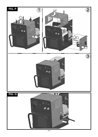
The only permitted way to lift the machine is that described in
adjusts the power according to the required welding
the "INSTALLATION" section of this handbook.
current/voltage.
7-
High frequency transformer: the primary winding is powered with
- It is forbidden to drag the engine-driven machine on streets.
the voltage converted by block 6; its function is to adapt the voltage
and current to the values needed for the arc welding procedure and
2. INTRODUCTION AND GENERAL DESCRIPTION
at the same time to form galvanic isolation of the welding circuit
This engine-driven welder is a power source for arc welding, built
from the power supply line
specifically for direct current (DC) MMA welding.
8-
Secondary rectifier bridge with levelling inductance: commutes the
The properties of this (INVERTER) adjustment system, such as high-
alternating voltage/current supplied by the secondary winding to
speed precise adjustment, mean that the engine-driven welder
very low ripple direct voltage/current.
produces excellent quality welds with coated electrodes (rutile, acid,
9-
Control and adjustment electronics: for instantaneous monitoring
basic, cellulose).
of transitory welding current values and comparison with setting
The machine also has an auxiliary outlet
for a direct current power
made by the operator; modulates the control impulses from the
supply to tools with universal motors (brushes)
such as angle
IGBT drivers used for adjustments.
grinders and drills.
Determines the dynamic response of the current while the
electrode is melting (instantaneous short circuits) and supervises
OPTIONAL ACCESSORIES:
the safety systems.
- MMA welding kit.
- TIG welding kit.
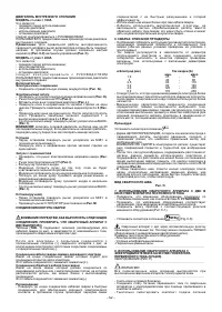
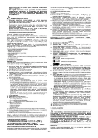
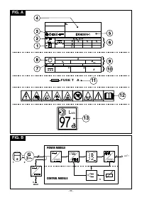
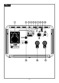
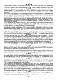
CONTROL AND ADJUSTMENT DEVICES AND CONNECTION TO
- Argon bottle adapter.
THE ENGINE-DRIVEN WELDER
- Pressure reduction valve.
Fig. C
- TIG torch.
1-
Auxiliary power outlet 230V DC (direct current).
- Wheels kit (Standard for the model with I max=200A).
2
2-
Auxiliary outlet fuse.
- AC power supply kit (only model with I max = 160A, I max = 200A).
2
2
3- GREEN LED:
when lit this indicates operation in direct current
generator mode.
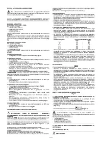
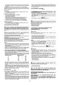
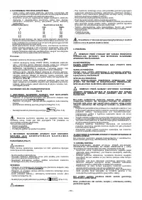
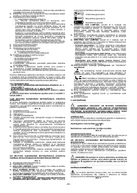
3. TECHNICAL DATA
4- GREEN LED:
when lit this indicates operation in alternating
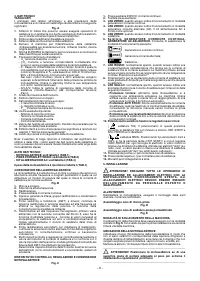
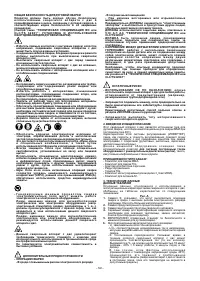
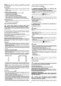
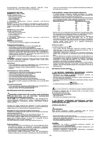
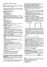
RATING PLATE
current (AC) generator mode. The AC power supply kit is supplied
The most important information regarding use and performance of the
as an optional accessory.
engine-driven welder are summarised on the rating plate and have the
5- GREEN LED:
when lit indicates operation in welding machine
following meanings:
mode.
Fig. A
6- Selector switch for DIRECT CURRENT GENERATOR AC
1
- Symbol S: means that it is possible to carry out welding operations
GENERATOR WELDING MACHINE.
Used to select the desired
in environments with a heightened risk of electric shock (e.g. close
operating mode:
to large metal objects).
2
- Symbol for intended welding procedure.
Direct current generator;
3
- Symbol indicating the internal structure of the welding machine.
4
- Serial number identifying the welding machine (essential for
Alternating current generator;
servicing and repairs, when ordering spare parts and identifying
the origin of the product).
5
- EUROPEAN standard of reference for the construction and safety
Welding machine.
of arc welding machines.
7- RED LED:
normally off, when on indicates overheating in the
6
- Performance of welding circuit:
alternator which shuts down both the welding current and the
- U : maximum no-load voltage.
0
auxiliary current. The machine remains switched on but does not
- I /U : Normalised current and corresponding voltage that may be
2
2
supply any current until a normal temperature is reached. Reset is
supplied by the welding machine during welding.
automatic.
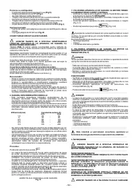
- X : Duty cycle: indicates the time for which the welding machine is
8-
Welding current adjustment potentiometer with graduated scale in
able to supply the corresponding current (same column). It is
Amps.; used for adjustment, also while welding.
expressed as %, based on a cycle of 10 minutes (e.g. 60% = 6
9 - YELLOW LED:
normally off, when on it indicates a fault that has
minutes work, 4 minutes pause; and so on).
shut down the welding current due to triggering of the following
If the utilisation factors (referred to a surrounding temperature of
safeguards:
40°C) are exceeded, the thermal relay will trigger (the engine-
- Thermal relay:
the temperature inside the engine-driven welder
driven welder will go into standby mode until the temperature
is too high. The machine stays on but does not supply any
returns within the accepted limits).
current until a normal temperature is reached. Reset is
- A/V-A/V: Indicates the adjustment range of the welding current
automatic.
(minimum-maximum) for the corresponding arc voltage.
- ANTI STICK safeguard:
automatically shuts down the welding
7
- Protection rating of case.
current if the electrode sticks to the material being welded, so
8
- Symbol for engine.
that it can be removed manually without ruining the electrode-
9
- Specifications for engine:
holder clamp.
- n: Rated load speed.
- Engine overspeed safeguard:
shuts down the welding current
- n : Rated idling speed.
0
supply until the engine speed returns to the rated values.
- P
: Maximum power of engine
1max
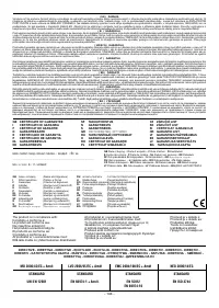
10- Function selector potentiometer and arc-force adjustment:
10
-Auxiliary power outlet:
- Symbol for direct current.
(
TIG welding). In this position the potentiometer enables TIG
- Rated output voltage.
welding with scratch strike. HOT START and ARC-FORCE are
- Rated output current.
disabled.
- Duty cycle.
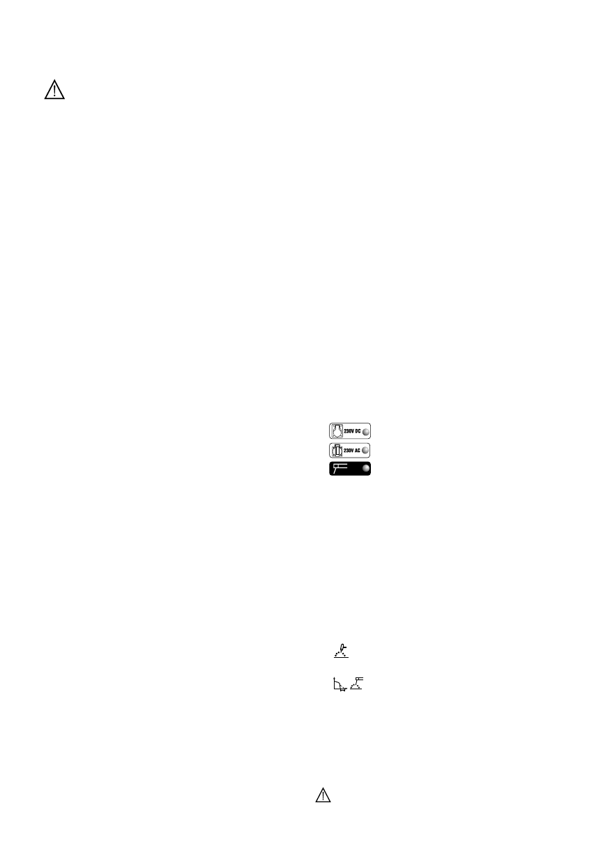
11
-Size of delayed action fuse to be used to protect the auxiliary
(
MMA welding). Positioning the potentiometer between 0
outlet.
and 100% gives an easy start (HOT START) and it is possibile to
12
-Symbols referring to safety standards, the meanings of which are
adjust the ARC-FORCE for all types of electrodes. At very low
given in section 1 "General safety rules".
values an optimal welding dynamic is obtained for “soft”
13
-Guaranteed sound power level for the engine-driven welder.
electrodes (e.g. rutile, stainless steel), at high values an optimal
welding dynamic is obtained for “hard” electrodes (e.g. acid, basic,
Note: The rating plate shown is just an example to show the meanings
cellulose).
of the symbols and figures; the exact technical specifications for your
11-
Positive quick connection (+) for connecting the welding cable.
welding machine should be read directly from the rating plate on the
12-
Negative quick connection (-) for connecting the welding cable.
engine-driven welder itself
13-
Terminal for earth connection.
OTHER TECHNICAL DATA:
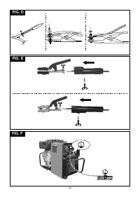
5. INSTALLATION
- ENGINE-DRIVEN WELDER: see table 1 (TAB.1)
________________________________________________________________________________
- ELECTRODE-HOLDER CLAMP: see table 2 (TAB.2)
- AC POWER SUPPLY KIT: see table 3 (TAB.3).
WARNING! ALL INSTALLATION OPERATIONS AND
The weight of the engine-driven welder is shown in table 1
- 4 -


