Сварочное оборудование Telwin INVERPULSE 625 MIG TIG MMA - инструкция пользователя по применению, эксплуатации и установке на русском языке. Мы надеемся, она поможет вам решить возникшие у вас вопросы при эксплуатации техники.
Если остались вопросы, задайте их в комментариях после инструкции.
"Загружаем инструкцию", означает, что нужно подождать пока файл загрузится и можно будет его читать онлайн. Некоторые инструкции очень большие и время их появления зависит от вашей скорости интернета.


- 9 -
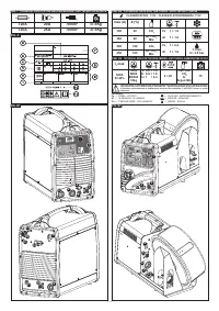
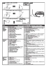
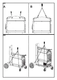
5.3 POSITION OF THE WELDING MACHINE
Choose the place to install the welding machine so that the cooling air inlets and
outlets are not obstructed (forced circulation by fan, if present); at the same time make
sure that conductive dusts, corrosive vapours, humidity etc. will not be sucked into
the machine.
Leave at least 250mm free space around the welding machine.
WARNING! Position the welding machine on a flat surface with
sufficient carrying capacity for its weight, to prevent it from tipping
or moving hazardously.
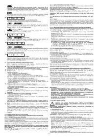
5.4 CONNECTION TO THE MAIN POWER SUPPLY
5.4.1 Note
- Before making any electrical connection, make sure the rating data of the welding
machine correspond to the mains voltage and frequency available at the place of
installation.
- The welding machine should only be connected to a power supply system with the
neutral conductor connected to earth.
- To ensure protection against indirect contact use residual current devices of the
following types:
- Type A (
) for single phase machines;
- Type B (
) for 3-phase machines.
- To comply with the requirements of the EN 61000-3-11 (Flicker) standard we
recommend connecting the welding machine to interface points of the power supply
that have an impedance of less than Zmax = 0.283 ohm.
- The welding machine does not fall within the requisites of IEC/EN 61000-3-12
standard.
Should it be connected to a public mains system, it is the installer’s responsibility
to verify that the welding machine itself is suitable for connecting to it (if necessary,
consult the distribution network company).
5.4.2 Plug and outlet
Connect a normalised plug (3P + T) having sufficient capacity to the power cable and
prepare a mains outlet fitted with fuses or an automatic circuit-breaker; the special
earth terminal should be connected to the earth conductor (yellow-green) of the power
supply line. The table (TAB.1) shows the recommended delayed fuse sizes in amps,
chosen according to the max. nominal current supplied by the welding machine, and
the nominal voltage of the main power supply.
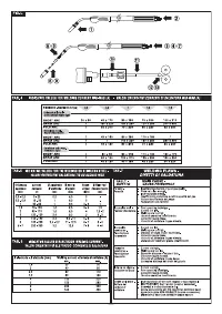
5.5 CONNECTION OF THE WELDING CABLES
WARNING! BEFORE MAKING THE FOLLOWING CONNECTIONS
MAKE SURE THE WELDING MACHINE IS SWITCHED OFF AND
DISCONNECTED FROM THE POWER SUPPLY OUTLET.
Table
(TAB. 1)
gives the recommended values for the welding cables (in mm
2
) .
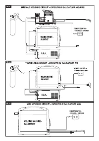
5.5.1 MIG-MAG WIRE WELDING (FIG.F)
5.5.1.1 Connecting the gas bottle
- Screw the pressure reducing valve onto the gas bottle, inserting the appropriate
adapter supplied as an accessory when Argon or an Ar/CO
2
mixture is used.
- Connect the gas inlet hose to the pressure reducing valve and tighten the supplied
clip; then connect the other end of the hose to the connector provided on the back
of the welding machine and tighten it with the supplied clip.
- Loosen the adjustment ring nut on the pressure reducing valve before opening the
gas bottle valve.
5.5.1.2 Connecting the torch
- Engage the torch with its dedicated connector by tightening the locking ring nut
manually as far down as it will go.
- Prepare the wire for loading the first time, by dismantling the nozzle and the contact
tip, to ease its exit.
- Welding power supply cable to the quick connector (+).
- Control cable to the corresponding connector.
- Water pipes for R.A. versions (water-cooled torch) with quick connectors.
- Make sure that the connectors are tightened properly so as to prevent overheating
and reduced efficiency.
- Connect the gas inlet hose to the pressure reducing valve and tighten the supplied
clip; then connect the other end of the hose to the connector provided on the back
of the welding machine and tighten it with the supplied clip.
5.5.1.3 Connecting the welding current return cable
- This is connected to the piece being welded or to the metal bench supporting it, as
close as possible to the join being made.
- This cable is connected to the terminal with the symbol (-).
5.5.2 TIG WELDING (FIG. G)
5.5.2.1 Connection to the gas bottle
- Screw the pressure reducing valve onto the gas bottle valve, inserting the
appropriate adapter supplied as an accessory, for when the gas used is Argon or an
Argon /CO
2
mixture.
- Connect the gas inlet pipe to the pressure-reducing valve and tighten the band
supplied; then connect the other end of the pipe to the connector on the back of the
welding machine and tighten it using the band supplied.
- Loosen the adjustment ring nut on the pressure-reducing valve before opening the
bottle valve.
5.5.2.2 Connecting the welding current return cable
- This is connected to the piece being welded or to the metal bench supporting it, as
close as possible to the join being made.
- This cable is connected to the terminal with the symbol (+).
5.5.2.3 Connecting the torch
- Connect the TIG torch to the quick connection (-) on the front panel of the welding
machine; complete the connection of the gas pipe and torch control cable.
5.5.3 MMA WELDING WITH COATED ELECTRODE (FIG. H)
5.5.3.1 Connecting the electrode-holder clamp
Practically all coated electrodes are connected to the positive pole (+) of the power
source; as an exception, electrodes with an acid coating are connected to the negative
pole (-).
Connect the electrode holder clamp cable to the quick connector (+) on the front panel.
Note:
In some cases, (-) polarity is recommended for the electrode holder clamp, so
check the electrode manufacturer’s instructions.
5.5.3.2 Connecting the welding current return cable
- This is connected to the piece being welded or to the metal bench supporting it, as
close as possible to the join being made.
- This cable is connected to the terminal with the symbol (-).
5.5.4 WARNINGS
- Turn the welding cable connectors right down into the quick connections , to ensure
a perfect electrical contact; otherwise the connectors themselves will overheat,
resulting in their rapid deterioration and loss of efficiency.
- The welding cables should be as short as possible.
- Do not use metal structures which are not part of the workpiece to substitute the
return cable of the welding current: this could jeopardise safety and result in poor
welding.
5.6 LOADING THE WIRE REEL (FIG. I)
WARNING! BEFORE STARTING THE OPERATIONS TO LOAD THE
WIRE MAKE SURE THE WELDING MACHINE IS SWITCHED OFF AND
DISCONNECTED FROM THE MAIN POWER SUPPLY OUTLET.
MAKE SURE THAT THE WIRE FEEDER ROLLERS, THE WIRE GUIDE HOSE AND
THE CONTACT TIP OF THE TORCH MATCH THE DIAMETER AND TYPE OF WIRE
TO BE USED AND MAKE SURE THAT THESE ARE FITTED CORRECTLY. WHEN
INSERTING AND THREADING THE WIRE DO NOT WEAR PROTECTIVE GLOVES.
- Open the reel compartment door.
- Position the wire reel on the spindle, holding the end of the wire upwards; make sure
the tab for pulling the spindle is correctly seated in its hole (1a).
- Release the pressure counter-roller/s and move it/them away from the lower roller/s
(2a).
- Make sure the puller roller is suitable for the wire being used (2b).
- Free the end of the wire and remove the distorted end with a clean cut and no burr;
turn the reel anti-clockwise and thread the end of the wire into the wire-guide infeed,
pushing it 50-100mm into the wire guide of the torch fitting (2c).
- Re-position the counter-roller/s, adjusting the pressure to an intermediate value,
and make sure that the wire is correctly positioned in the groove of the lower roller
(3).
- Use the adjustment screw located at the centre of the spindle to apply a slight
braking pressure on the spindle itself (1b).
- Remove the nozzle and contact tip (4a).
- Insert the welding machine plug in the power supply outlet, switch on the welding
machine, press the torch button and wait for the end of the wire to pass through the
whole of the wire guide hose and protrude by 10-15 cm from the front part of the
torch, release the button.
WARNING! During these operations the wire is live and subject to
mechanical stress; therefore if adequate precautions are not taken
the wire could cause hazardous electric shock, injury and striking of
electric arcs:
- Do not direct the mouthpiece of the torch towards parts of the body.
- Keep the torch away from the gas bottle.
- Re-fit the contact tip and the nozzle onto the torch (4b).
- Check that wire feed is regular; set the roller and spindle braking pressure to the
minimum possible values making sure that the wire does not slide in the groove and
when feed is halted the loops of wire are not loosened by excessive reel inertia.
- Cut the end of the wire so that 10-15 mm protrude from the nozzle.
- Close the reel compartment door.
5.7 REPLACING THE LINER IN THE TORCH (FIG. L)
Before proceeding to replace the hose, lay out the torch cable straight without any
bends.
5.7.1 Coiled hose for steel wires
1- Unscrew the nozzle and contact tip on the torch head.
2- Unscrew the hose locking nut on the central connector and remove the old hose.
3- Insert the new hose into the cable-torch duct and push it gently until it comes out
of the torch head.
4- Tighten up the hose locking nut by hand.
5- Trim off all the excess protruding hose pressing it slightly; remove it from the torch
cable again.
6- Smooth the part where the hose was cut and reinsert it into the cable-torch duct.
7- Tighten up the nut again using a spanner.
8- Reassemble the contact tip and nozzle.
5.7.2 Synthetic hose for aluminium wires
Carry out operations
1, 2, 3
as given for the steel hose (ignore operations
4, 5, 6, 7, 8
).
9- Re-tighten the contact tip for aluminium, making sure it comes into contact with the
hose.
10- At the other end of the hose (torch connector end) insert the brass nipple and the
OR ring and, keeping slight pressure on the hose, tighten the hose locking nut.
The excess part of the hose will be removed to size later on (see (13)).
Extract the capillary pipe for steel hoses from the wire feeder torch connector.
11- THE CAPILLARY PIPE IS NOT REQUIRED for aluminium hoses of diameter 1.6-
2.4mm (coloured yellow); the hose is therefore inserted into the torch connector
without it.
Cut the capillary pipe for aluminium hoses of diameter 1-1.2mm (coloured red) to
approx. 2mm shorter than the steel pipe, and insert it into the free end of the hose.
12- Insert and lock the torch into the wire feeder connector, mark the hose at 1-2mm
from the rollers, take the torch out again.
13- Cut the hose to the required size, without distorting the inlet hole.
Reassemble the torch in the wire feeder connector and assemble the gas nozzle.
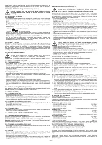
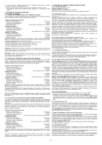
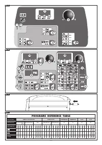
6. WELDING: DESCRIPTION OF THE PROCEDURE
6.1 MIG-MAG WELDING
6.1.1 SHORT ARC TRANSFER MODE
The melting of the electrode wire and the detachment of the drop is produced by
repeated short circuits (up to 200 times per second) from the tip of the wire to the
molten pool.
Carbon and mild steels
- Suitable wire diameter:
0.6-1.2mm
- Welding current range:
40-210A
-
Arc voltage range:
14-23V
- Suitable gases:
CO
2
, mix Ar/CO
2
, Ar/CO
2
/O
2
Stainless steels
- Suitable wire diameter:
0.8-1mm
- Welding current range:
40-160A
-
Arc voltage range:
14-20V


