Сварочное оборудование Telwin INVERPULSE 625 MIG TIG MMA - инструкция пользователя по применению, эксплуатации и установке на русском языке. Мы надеемся, она поможет вам решить возникшие у вас вопросы при эксплуатации техники.
Если остались вопросы, задайте их в комментариях после инструкции.
"Загружаем инструкцию", означает, что нужно подождать пока файл загрузится и можно будет его читать онлайн. Некоторые инструкции очень большие и время их появления зависит от вашей скорости интернета.


- 10 -
- Suitable gases:
mix Ar/O
2
, Ar/CO
2
(1-2%)
Aluminium and alloys
- Suitable wire diameter:
0.8-1.6mm
- Welding current range:
75-160A
-
Arc voltage range:
16-22V
- Suitable gases:
Ar 99.9%
Generally, the contact tip should be flush with the nozzle or protrude slightly when
using the thinnest wires and lowest arc voltages; the length of free wire (stick-out) will
normally be between 5 and 12mm.
In MANUAL MODE (“PRG 0”) adjust the reactance value:
- 5%-60% with carbon steel wires of diameter 0.8-1mm.
- 50%-80% with carbon steel wires of diameter 1.2-1.6mm.
- 60%-80% with stainless steel and aluminium wires.
Application:
Welding in all positions, on thin material or for the first passage in
bevelled edges, with the advantage of limited heat transfer and highly controllable
pool.
Note:
SHORT ARC transfer for welding aluminium and alloys should be used with
great care (especially with wires of diameter >1mm) because the risk of melting
defects may arise.
6.1.2 SPRAY ARC TRANSFER MODE
Higher voltages and currents than for ”short arc” are used here to achieve the melting
of the wire. The wire tip does not come into contact with the molten pool; an arc forms
from the tip and through it flows a stream of metallic droplets. These are produeced by
the continuous melting of the electrode wire without short-circuits involved.
Carbon and mild steels
- Suitable wire diameter:
0.8-1.6mm
-
Welding current range:
180-450A
-
Arc voltage range:
24-40V
-
Suitable gases:
mix Ar/CO
2
, Ar/CO
2
/O
2
Stainless steels
- Suitable wire diameter:
1-1.6mm
-
Welding current range:
140-390A
-
Welding voltage range:
22-32V
-
Suitable gases:
mix Ar/O
2
, Ar/CO
2
(1-2%)
Aluminium and alloys
- Suitable wire diameter:
0.8-1.6mm
-
Welding current range:
120-360A
-
welding voltage range:
24-30V
-
suitable gases:
Ar 99.9%
The contact tip should generally be 5-10mm inside the nozzle, the higher the arc
voltage the further inside; the length of free wire (stick-out) should normally be
between 10 and 12mm.
In MANUAL MODE (“PRG 0”), once the wire feed rate and arc voltage parameters
have been selected correctly (i.e. with compatible values), the selected value of the
reactance is immaterial.
Application:
Horizontal welding with thicknesses of at least 3-4mm (very fluid pool);
execution rate and deposit rate are very high (high heat transfer).
6.1.3 PULSE ARC TRANSFER MODE
This is a “controlled” transfer situated in the “spray arc” transfer area (modified spray
arc) and therefore has the advantages of speedy melting and lack of projections,
extending to significantly low current values so as to satisfy many typical “short arc”
applications as well.
Every current impulse corresponds to the separation of a single drop from the wire
electrode; the phenomenon occurs with a frequency that is proportional to the wire
feed rate with the variation rule related to the type and diameter of the wire itself
(typical frequency values: 30-300Hz).
Carbon and mild steels
- Suitable wire diameter:
0.8-1.6mm
-
Welding current range:
60-360A
-
Arc voltage range:
18-32V
-
Suitable gases:
mix Ar/CO
2
, Ar/CO
2
/O
2
(Co
2
max 20%)
Stainless steels
- Suitable wire diameter:
0.8-1.2mm
-
Welding current range:
50-230A
-
Welding voltage range:
17-26V
-
Suitable gases:
mix Ar/O
2
, Ar/CO
2
(1-2%)
Aluminium and alloys
- Suitable wire diameter:
0.8-1.6mm
-
Welding current range:
40-320A
-
welding voltage range:
17-28V
-
suitable gases:
Ar 99.9%
Normally the contact pipe should be 5-10mm inside the nozzle, the higher the arc
voltage, the further inside; the length of free wire (stick-out) will normally be between
10 and 12mm.
Application
: “horizontal” welding on medium-low thicknesses and on heat-sensitive
materials,
particularly suitable for welding light alloys (aluminium and its alloys)
also on thicknesses below 3mm
.
6.1.4 ADJUSTING THE WELDING PARAMETERS IN MIG-MAG
6.1.4.1 Protective gas
The gas flow rate should be:
short arc:
8-14 l/min
spray arc and pulse arc:
12-20 l/min
depending on welding current intensity and nozzle diameter.
6.1.4.2 Welding current
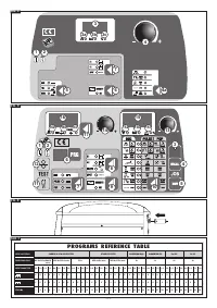
Welding current is adjusted by the operator by turning the encoder knob
(FIG. D
(14))
. When SPRAY/SHORT ARC is selected, each turn of the encoder knob
(14)
corresponds to a wire feed rate adjustment (m/minute), which is shown on the display
(16)
; during welding, the display automatically switches to the actual current value
(amps).
When PULSE ARC or
PULSE ARC PULSE-ON-PULSE
is selected, each time the
encoder knob
(14)
is turned this corresponds to an adjustment of welding current,
which is shown on the display
(16)
; during welding, the display automatically switches
to the actual current value.
In both modes it is possible to press key (17) to pass to regulation of thickness in mm
(LED (16b) lit up) using the encoder (14). The machine automatically calculates the
current required to weld this thickness. Also in this case the display will switch to the
actual current (amps.) during welding.
It should be pointed out that in all the synergic programs the maximum and minimum
values for the settings (m/minute, amps or thickness in mm) are programmed in the
factory and cannot be changed by the user.
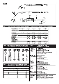
Indicative values for the current with the most commonly used wires are given in the
table
(TAB. 4)
.
6.1.4.3 Arc voltage and Pinch-off
In MIG-MAG pulse-arc and pulse-on-pulse synergy programs
(10d)
these two
parameters determine the dimension of the arc
during welding
The arc voltage indicates the distance of the wire from the piece. The discretion margin
of the operator is limited to the simple correction from -5% to +5% of the voltage value
that is preset in each program to adapt the effective length of the arc for specific needs
if necessary. The higher the value the farther the wire from the piece.
In the “PRG 0” manual program the arc voltage is defined by setting a suitable value
for the wire feed rate, selected using the formula
U
2
= ( 14+0,05 I
2
) where:
- U
2
= Arc voltage in volts.
- I
2
= Welding current in amperes
It must be considered that the loaded voltage (during welding) is to 2-4V less than the
selected loadless voltage value.
The pinch-off instead determines the arc concentration or width; the correction range
of this parameter goes from -10% to +10% of the program default value. The higher
the value, the more concentrated the arc will be.
6.1.5 BI-LEVEL AND PULSE ON PULSE OPERATION
Bi-level operation:
Set using key (
FIG. D (8))
and can be selected in MIG-MAG pulse
arc and short arc modes. The welding cycle begins by pressing and releasing the
torch pushbutton (like the 4-stroke), the initial work point of the welding machine is
equal to the main welding level
(FIG. D (LED (10a))
and the machine shows current
and voltage of this work point. Keeping the torch pushbutton pressed for less than 0.5
seconds makes the machine change the work point from the main to the secondary
level
(FIG. D (LED (10b))
, showing the secondary level current and voltage on the
display. With each subsequent push of the torch pushbutton, the machine continues
passing from one level to another until the pushbutton is kept pressed for longer than
0.5 seconds, starting the down slope of the current thus ending the welding.
During welding, and even if the machine shows the immediate current and voltage
values, only the arc current and voltage of the main welding level can be varied.
MIG-MAG Pulse on Pulse operation:
can be activated using key
(FIG. D (7))
together with the MIG-MAG Pulse arc LED. This is a special type of bi-level mode
because also in this case we have two work points set with the same criteria as the
bi-level
(FIG. D (LED (10a) and (10b))
.
The duration of each level t
1
and t
2
can both
be set
(FIG. D (LED (10c) and (10d))
and are not set manually, as happens instead
with bi-level. During welding the machine therefore continues switching the working
point automatically from the main level (duration t
1
) to the secondary level (duration t
2
).
The phenomenon created is that of having a pulsation in a pulsation, hence the name.
By setting the two levels and the two durations correctly it is possible to obtain wave
welding that is very similar to TIG welding
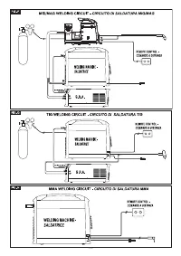
6.2 TIG WELDING (DC)
After making the welding circuit connections as described in section 5.5.2 it is
necessary to:
- Select the TIG welding procedure on the welding machine control panel
(FIG.C (5))
.
- Set the welding current to the desired value using the encoder knob
(FIG. C (4))
,
(the value can always be adjusted during welding as well).If necessary insert the
current down slope using the key
(FIG. C (4a))
(momentary indication on the display
(FIG. C (3))
.
6.2.1 LIFT strike
Place the tip of the electrode on the piece, using slight pressure. Press the torch button
right down and lift the electrode by 2-3 mm with a slight delay, so that the arc strikes.
The welding machine will first output a base current I
BASE
, after a few moments the
current output will be equal to the welding current setting. At the end of the cycle the
current will decrease according to the slope down setting.
Table
(TAB. 5)
summarises some indicative data for welding stainless or high alloy
steel.
6.3 WELDING WITH MMA COATED ELECTRODE
After making the welding circuit connections as described in section 5.5.3 select the
MMA procedure using the corresponding button
(FIG. C (5)):
Set the welding current to the desired value using the encoder knob
(FIG.
C (4))
and
any possible “ARC FORCE” dynamic overcurrent can be varied from between 0 and
100% using the encoder knob
(FIG. C (4)),
with a momentary indication of the value
on the display
(FIG. C (3))
.
The table
(TAB. 6)
summarises some indicative values for the current in relation to
electrode diameter.
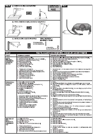
6.4 WELD QUALITY
The quality of the weld seam, and the amount of spatter, is mainly determined by the
balance of the welding parameters: current (wire feed rate), wire diameter, arc voltage
etc.
In addition, the position of the torch should be adjusted as shown in
Fig. M
, to prevent
excessive spray production and flaws in the seam.
The welding rate (i.e. advancement speed along the join) should also be taken into
consideration. This is a determining factor for correct penetration and for the shape
of the seam itself.
The most common welding flaws are summarised in the table (
TAB. 7).
7. MAINTENANCE
WARNING! BEFORE CARRYING OUT MAINTENANCE OPERATIONS
MAKE SURE THE WELDING MACHINE IS SWITCHED OFF AND
DISCONNECTED FROM THE MAIN POWER SUPPLY.
7.1 ROUTINE MAINTENANCE
ROUTINE MAINTENANCE OPERATIONS CAN BE CARRIED OUT BY THE
OPERATOR.
7.1.1.Torch
- Do not put the torch or its cable on hot pieces; this would cause the insulating
materials to melt, making the torch unusable after a very short time.
- Make regular checks on the gas pipe and connector seals.
- Every time the wire reel is changed, blow out the wire-guide hose using dry
compressed air (max. 5bar) to make sure it is not damaged.
- At least once a day, check the wear and correct assembly of the parts at the end of
the torch: nozzle, contact tip, gas diffuser.
7.1.2 Wire feeder
- Make frequent checks on the state of wear of the wire feeder rollers, regularly


