Сварочное оборудование Telwin INVERPULSE 625 MIG TIG MMA - инструкция пользователя по применению, эксплуатации и установке на русском языке. Мы надеемся, она поможет вам решить возникшие у вас вопросы при эксплуатации техники.
Если остались вопросы, задайте их в комментариях после инструкции.
"Загружаем инструкцию", означает, что нужно подождать пока файл загрузится и можно будет его читать онлайн. Некоторые инструкции очень большие и время их появления зависит от вашей скорости интернета.


- 7 -
removed.
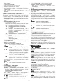
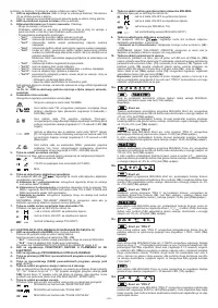
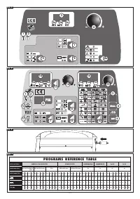
2- LED indicating voltage presence at output
(output active).
3- 3-digit alphanumeric display
. This shows:
- The welding current in amperes.
The indicated value is the set value when the machine is in no-load mode, and
is the true value during operation.
- An alarm message with the following code:
-
”AL1” :
thermal relay cut in for primary circuit.
-
”AL2” :
thermal relay cut in for secondary circuit.
-
”AL3” :
overvoltage safeguard one power line triggered.
-
”AL4” :
undervoltage safeguard on power line triggered.
-
”AL5” :
model with GRA: safeguard triggered due to insufficient pressure
in water-cooled circuit in torch. Reset is not automatic.
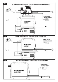
model without GRA: no connection between the polarisation
connector and the machine (FIG. E).
-
“AL9” :
magnetic components safeguard triggered.
-
“AL10” :
fault in serial line: serial line disconnected.
-
“AL11” :
phase failure safeguard on power line triggered.
-
“AL12” :
fault in serial line: data error.
-
“AL13” :
too much dust deposited inside welding machine, reset by
- cleaning inside the machine;
- key for selecting the parameters on the control panel.
The signal
“AL11”
and
“OFF”
may appear for a few seconds when the welding
machine is being switched off.
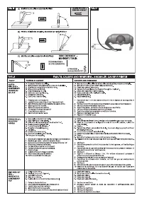
3a, 3b, 3c – LED’s indicating current unit of measurement (amperes,
seconds, percentage).
4- Encoder control knob.
Makes it possible to adjust the welding parameters
(4a)
.
: Welding current in TIG/MMA mode.
: In tig mode it is used to reduce the current gradually when the
torch button is released (adjustment range 0-3 seconds) and the
LED (3b) on.
: In TIG mode this parameter corresponds to “Post-gas”, and is
used to adjust the time for which protective gas will flow after
welding stops (adjustment range 0.1-10 seconds and LED (3b)
on).
: This is enabled only and exclusively if the “SPOT” mode has
been selected with key (7). It is used for TIG spot welding with
welding time control (adjustment range 0.1-10 seconds and LED
(3b) on).
: With MMA electrode operation, the parameter takes the value of
“;Arc force”, so that it is possible to make the setting for dynamic
overcurrent (adjustment range 0-100% and LED (3c) on).
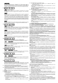
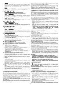
5- Key for selecting welding procedure.
When this key is pressed the LED corresponding to the intended welding mode
will light up:
: MMA” coated electrode
: TIG-DC with arc striking at contact (LIFT-ARC).
: MIG.
6- Key for switching on the remote control
.
With LED
on, adjustments can only be by remote control i.e.:
a) Single potentiometer control: it is used to adjust the welding current in TIG/
MMA mode.
b) Control by two potentiometers: it is used to adjust the TIG/MMA welding
current and adjust the SLOPE DOWN in TIG or ARC FORCE in MMA
(automatic LED parameter selection).
c) Pedal control: it is used to adjust the welding current in TIG/MMA mode.
NOTE: It is only possible to select REMOTE if a remote control is actually
connected to the socket.
7- Key for selecting TIG torch button control mode.
Pressing the key lights up the LED that corresponds to:
: 2-stroke operation, ON-OFF with pushbutton pressed.
: 4-stroke operation, ON-OFF with pushbutton released.
: TIG spot welding.
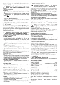
4.2.1 CONTROL PANEL OF THE WIRE FEEDER (FIG. D)
1- ALARM signalling LED
(machine output is blocked).
Resetting is automatic when the reason for alarm activation has ceased.
Exclusive alarm messages indicated on displays
(15)
and
(16)
:
-
“AL7” :
overcurrent safeguard intervention during MIG-MAG welding.
-
“AL8” :
serial line fault: torch is shorting.
For the remaining messages refer to “WELDING MACHINE CONTROL PANEL”
(par. 4.2).
2- VOLTAGE PRESENT IN THE TORCH OR AT THE ELECTRODE signalling
LED.
3- WELDING MACHINE PROGRAMMING signalling LED.
4 - RECALL key of the personalised welding programs (see section 4.3.2.4).
5- SAVE key of the personalised welding programs (see section 4.3.2.3).
6- Welding program selection key and 2 digit display.
The display shows the numbers between “0” and “36” when the key is pressed
in succession. A synergic welding program is associated with each number
from “1” to “36”
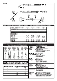
(see TAB. 3)
while manual operation of the welding machine is
associated with the number “0”, in which all the parameters can be set by the
operator (only in MIG-MAG SHORT and SPRAY ARC).
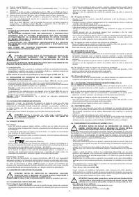
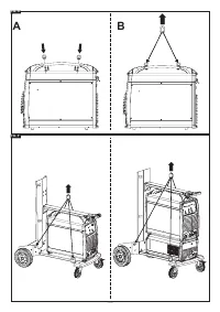
7- Welding procedure selection key.
When this key is pressed the LED corresponding to the intended welding mode
will light up:
: MIG-MAG with “SHORT/SPRAY ARC” mode.
: MIG-MAG with “PULSE ARC” mode.
: MIG-MAG with “PULSE ON PULSE” mode.
8- Key for selecting MIG-MAG torch button control mode.
When this key is pressed the LED will light up corresponding to:
: 2- stroke operation, ON-OFF with button pressed.
: 4- stroke operation, ON-OFF with button released.
: bi-level operation for MIG-MAG, TIG.
: MIG-MAG (SPOT) welding.
9- Key for switching on remote control.
When LED
is on, adjustments can only be made by remote control,
i.e.:
- control by two potentiometers:
replaces the function of encoder knobs
(14)
and
(13).
NOTE: It is only possible to select REMOTE if a remote control is actually
connected to the corresponding socket.
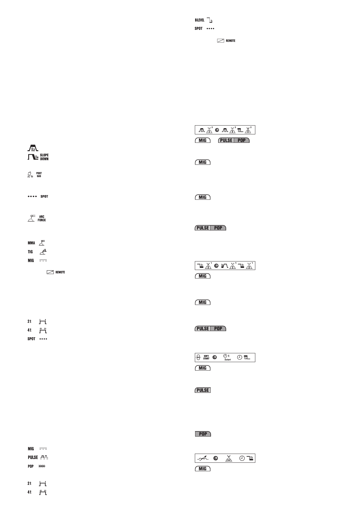
10- Key for selecting welding parameters.
Pressing the key repeatedly will light up one of the LED’s from
(10a)
to
(10h)
,
each associated with a specific parameter. Settings of the value of each activated
parameter can be carried out using the knob
(13)
and shown on the display
(15)
.
During these settings the knob
(14)
adjusts the main welding level shown on the
display
(16)
either current or wire feed rate (see description at point
(14)
), except
for
(10b)
.
Knob
(14)
can only be used to adjust the secondary level when LED
(10b)
is on
(see description of LED
(10b)
).
Note:
Parameters that cannot be modified by the operator, depending on
whether you are working with a synergic programme or in manual mode (“PRG”
0) are automatically excluded so that they cannot be selected; the corresponding
LED will not light up.
10a-
This parameter is displayed automatically during MIG-MAG welding operations,
and shows the actual arc voltage (LED (15a) is on).
Adjustments:
Short arc
When setting a MIG-MAG Short Arc synergic programme this parameter is used
to set the correction to be made to the arc length as calculated in synergy (range
from -5% to +5%) (LED
(15c)
on).
In the same mode, setting bi-level mode will cause the parameter to take the
value of arc length correction at the main welding level as calculated in synergy
as above (range from -5% to +5%) (LED
(15c)
on).
Short arc “PRG 0”
Also in MIG-MAG Short Arc mode, manual programming “PRG 0”, this parameter
is used to set the actual arc voltage (range 10-40) (LED
(15a)
on).
In the same mode, setting bi-level mode will cause the parameter to take the
value of actual arc length at the main welding level as calculated in synergy as
above (range 10-40) (LED
(15a)
on).
When setting a MIG-MAG Pulse Arc synergic programme this parameter is used
to set the correction to be made to the arc length as calculated in synergy (range
from -5% to +5%) (LED
(15c)
on).
In the same mode, setting bi-level, pulse on pulse or T
start
mode will cause the
parameter to take the value of arc length correction at the main welding level as
calculated in synergy as above (range from -5% to +5%) (LED
(15c)
on).
10b-
Short arc
For synergic MIG-MAG short arc programmes, setting bi-level mode will make it
possible to adjust the current/wire feed rate (using knob
(14)
) and to correct arc
length (using knob
(13)
) for the secondary welding level as calculated in synergy
(range from -5% to +5%) (LED
(15c)
on).
Short arc “PRG 0”
When manual programming “PRG 0” is selected with bi-level mode, this
parameter is used to adjust wire feed rate (using knob
(14)
, (LED
16c
) on) and
actual arc voltage (using knob
(13)
) for the secondary welding level I
1
(range 10-
40) ((LED
(15a)
on)
.
In
MIG-MAG pulse arc mode, setting bi-level, pulse on pulse or T
start
mode will
enable adjustment of currents I
1
and I
S
(I
start
) (using knob
(14)
) and correction of
arc length (using knob
(13)
) for the secondary welding level, as calculated in
synergy (range from -5% to +5%)(LED
(15c)
on).).
10c-
Short arc “PRG 0”
In manual mode, “PRG 0”, this parameter is used to adjust wire feed rate as
welding starts, in order to optimise arc strike (adjustment 1-100% and LED
(15c)
on).
In MIG-MAG Pulse Arc 2-STROKE mode this parameter is used to adjust the
length of start current time (T
start
). If the parameter is set to zero, the function
is disabled, while with any setting greater than zero (adjustment range 0.1-
3 seconds) it is possible to select LED
(10b)
in order to set the arc voltage
correction and the start current value (secondary level). The start current can
be set at a higher or lower value than the main welding value; a higher start
current is very useful, especially when welding aluminium and its alloys, making
it possible to heat the piece more quickly (“Hot start”).
In MIG-MAG Pulse on Pulse mode the parameter can be used to adjust the
length of main welding current time (adjustment range 0.1-10 seconds and LED
(15b) on).
10d-
Short arc “PRG 0”
In MIG-MAG “PRG 0” manual mode the parameter is used to adjust electronic
reactance (adjustment range 20-80% and LED
(15c)
on). The higher the value,
the hotter will be the weld pool. In bi-level mode electronic reactance has the
same setting for both levels.


