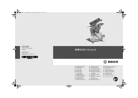
Пилы торцовочные Bosch GTM 12 JL - инструкция пользователя по применению, эксплуатации и установке на русском языке. Мы надеемся, она поможет вам решить возникшие у вас вопросы при эксплуатации техники.
Если остались вопросы, задайте их в комментариях после инструкции.
"Загружаем инструкцию", означает, что нужно подождать пока файл загрузится и можно будет его читать онлайн. Некоторые инструкции очень большие и время их появления зависит от вашей скорости интернета.


English |
45
Bosch Power Tools
1 609 92A 1T0 | (28.10.15)
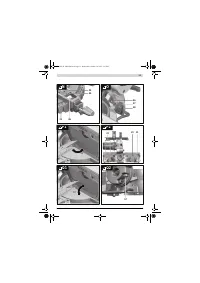
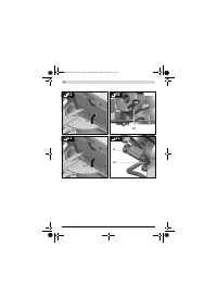
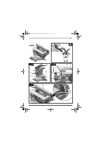
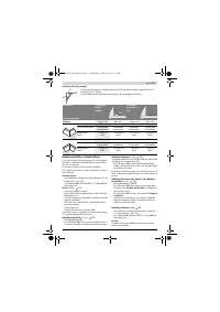
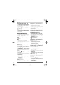
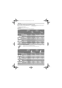
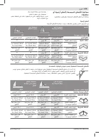
Ceiling Strips/Mouldings (According to US Standard)
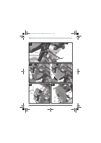
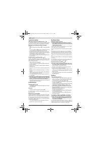
Checking and Adjusting the Basic Adjustment
To ensure precise cuts, the basic adjustment of the machine
must be checked and adjusted as necessary after intensive
use.
A certain level of experience and appropriate specialty tools
are required for this.
A Bosch after-sales service station will handle this mainte-
nance task quickly and reliably.
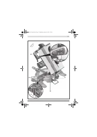
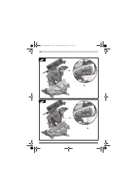
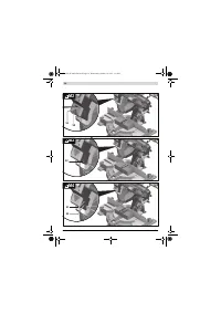
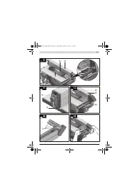
Adjusting the Laser
– Bring the power tool into the table saw working position.
(see “Working Position”, page 47)
– Turn the saw table
22
to the 0 ° detent
27
. The lever
26
must be felt to engage in the detent.
Checking:
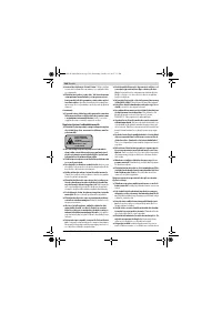
(see figure
M1)
– Draw a straight cutting line on the workpiece.
– Push button
17
and slowly guide the tool arm downward
with the handle
18
.
– Align the workpiece in such a manner that the teeth of the
saw blade are in alignment with the cutting line.
– Hold the workpiece in this position and slowly guide the
tool arm upward again.
– Clamp the workpiece.
– Switch the laser beam on with switch
36
.
The laser beam must be in alignment with the cutting line on
the workpiece over the complete length, also when the tool
arm is lowered.
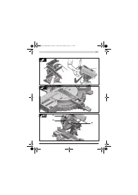
Adjusting the Parallelism:
(see figure
M2)
– Undo the rubber cap
50
.
– Screw the adjustment screw
51
in or out using a suitable
screwdriver until the laser beam is parallel with the cutting
line on the workpiece over the complete length.
Adjusting the Flush Levelling:
(see figure
M3)
An adjustment screw
52
, which is located below the opening
marked with “R/L”, is used for adjustment of the flush leve-
ling.
– Screw the adjustment screw
52
in or out with the slotted
screwdriver provided until the parallel laser beam is flush
with the cutting line on the workpiece over the complete
length.
One rotation in anticlockwise direction moves the laser beam
from left to right; one rotation in clockwise direction moves
the laser beam from right to left.
Adjusting the Lateral Deviation while Moving the Tool
Arm:
(see figure
M4)
– Open the side rubber cap
53
.
– If the laser beam
moves towards the left
when lowering
the tool arm, turn adjustment screw
54
clockwise using a
suitable screwdriver.
If the laser beam
moves towards the right
, turn adjust-
ment screw
54
anticlockwise.
– After adjusting, check the flushness with the cutting line
again. If required, align the laser beam with the adjustment
screw
52
again.
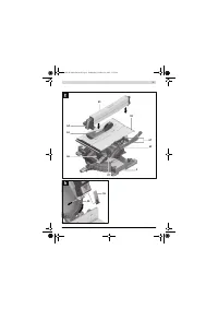
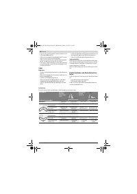
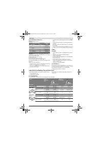
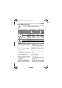
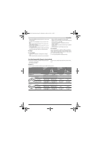
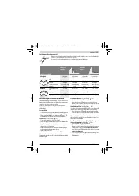
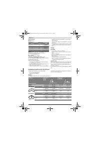
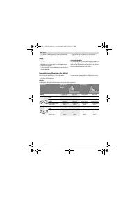
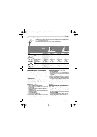
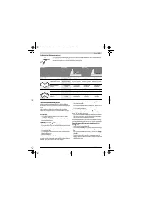
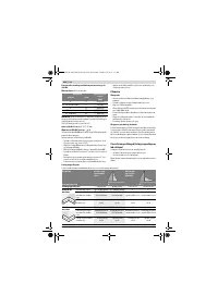
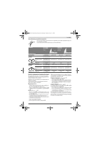
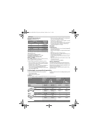
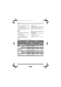
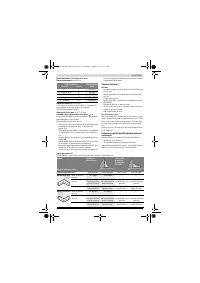
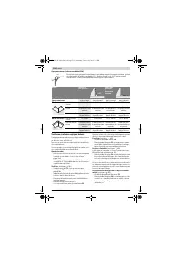
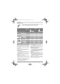
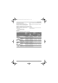
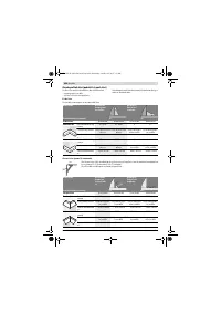
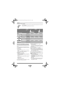
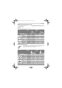
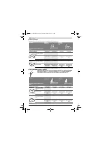
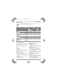
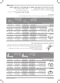
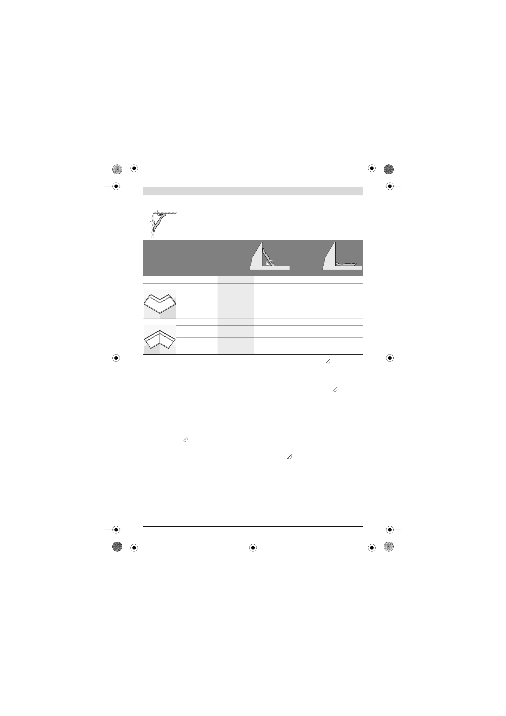
When the ceiling strips/mouldings are to be sawn lying flat on the saw table, the standard mitre angles
of 31.6 ° (horizontal) and 33.9 ° (vertical) must be set.
The following table contains instructions for sawing ceiling strips/mouldings.
Settings
Placed
against the
fence
Lying flat on
the saw table
Bevel angle
0 °
33,9 °
Ceiling strip/moulding
Left side
Right side
Left side
Right side
Inner corner
Horizontal mitre angle
45 ° right
45 ° left
31.6 ° right
31.6 ° left
Positioning of work-
piece
Bottom edge
against the fence
Bottom edge
against the fence
Upper edge against
the fence
Bottom edge
against the fence
The finished work-
piece is located ...
... to the right of the
cut
... to the left of the
cut
... to the left of the
cut
... to the left of the
cut
Outer corner
Horizontal mitre angle
45 ° left
45 ° right
31.6 ° left
31.6 ° right
Positioning of work-
piece
Bottom edge
against the fence
Bottom edge
against the fence
Bottom edge
against the fence
Upper edge against
the fence
The finished work-
piece is located ...
... to the right of the
cut
... to the left of the
cut
... to the right of the
cut
... to the right of the
cut
52°
38°
52°
OBJ_BUCH-1688-006.book Page 45 Wednesday, October 28, 2015 3:13 PM
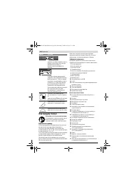
Содержание
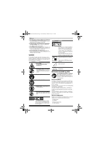
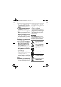
- 275 Безопасность людей
- 276 Не становитесь на электроинструмент.
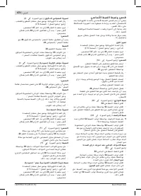
- 277 Всегда распиливайте только одну деталь.; Символы; Применение по назначению; Символ
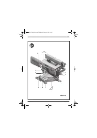
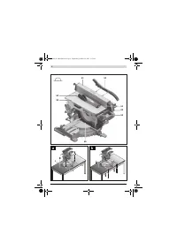
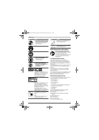
- 278 Изображенные составные части; Части торцовочно-усовочной пилы
- 279 Продольный упор; Технические данные; Применяйте средства защиты органов слуха!; Монтаж и транспорт; Комплект поставки; Комбинированная пила; Размеры пильных дисков
- 280 Монтаж на верстаке производства Bosch; Отсос пыли и стружки; Избегайте скопления пыли на рабочем месте.; Монтаж отдельных частей
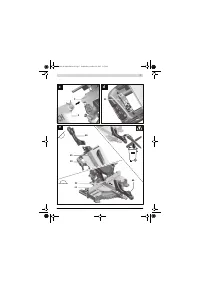
- 281 Демонтаж пильного диска
- 282 Подготовка к эксплуатации; Отпустите; Настройка угла распила; Регулировка с помощью шкалы точной настройки
- 283 Включение электроинструмента; Угол распила
- 284 Пиление; Торцование
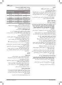
- 285 Основные настройки – контроль и коррекция; Настройки
- 286 Настройка упорной планки
- 287 симальная высота детали; Включения
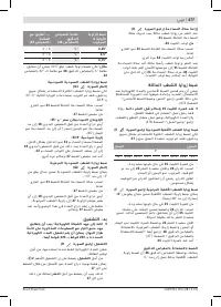
- 288 Указания по применению; Общие указания для пиления; Выполнение прямых пропилов
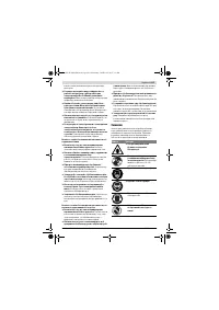
- 289 Техобслуживание и сервис; Техобслуживание и очистка; Очистка; Принадлежности; Россия
- 290 Беларусь; Утилизация
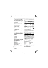
Характеристики

Остались вопросы?Не нашли свой ответ в руководстве или возникли другие проблемы? Задайте свой вопрос в форме ниже с подробным описанием вашей ситуации, чтобы другие люди и специалисты смогли дать на него ответ. Если вы знаете как решить проблему другого человека, пожалуйста, подскажите ему :)


