Электропилы Bosch PTS 10 - инструкция пользователя по применению, эксплуатации и установке на русском языке. Мы надеемся, она поможет вам решить возникшие у вас вопросы при эксплуатации техники.
Если остались вопросы, задайте их в комментариях после инструкции.
"Загружаем инструкцию", означает, что нужно подождать пока файл загрузится и можно будет его читать онлайн. Некоторые инструкции очень большие и время их появления зависит от вашей скорости интернета.


34
| English
1 609 92A 039 | (28.9.12)
Bosch Power Tools
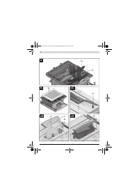
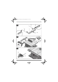
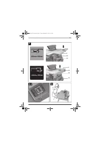
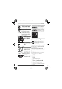
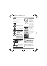
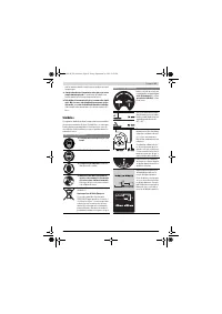
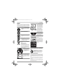
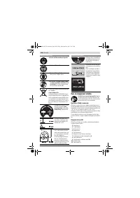
Adjusting the Parallel Fences
Parallel Fence 8 (see figure E)
The mark in the lens
57
indicates the set clearance of the par-
allel guide to the saw blade on the scale
13
.
– Position the parallel fence on the requested side of the the
saw blade. (also see “Mounting the Parallel Guide”,
page 32)
– Pull the clamping knob
44
upward to release the lock and
move the parallel fence until the lens
57
indicates the re-
quested clearance to the saw blade.
– To lock the parallel guide, press the clamping handle
44
down.
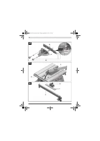
Parallel Fence 9 at the Table Width Enlargement
(see figure F)
The parallel fence
9
can be positioned either left or right from
the table width enlargement
10
.
The colour of the sticker on the parallel fence corresponds
with the colours of the scale
58
on the front guide rod. De-
pending on the position of the parallel fence, the scale indi-
cates the clearance to the saw blade.
– Screw the parallel fence at the requested position to the ta-
ble width enlargement.
– Grasp the table width enlargement centrally and from be-
low, and pull it out until the black or grey scale indicates the
requested clearance to the saw blade.
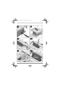
Adjusting the Auxiliary Stop 7
When sawing narrow workpieces and bevel angles
, the
auxiliary stop
7
must be mounted to the parallel guide
8
.
(see figure g2)
When sawing workpieces, these can become jammed be-
tween the parallel guide and the saw blade, be caught by the
rotating saw blade, and be thrown from the machine.
Therefore, adjust the auxiliary stop
7
in such a manner that its
guiding end is located between the front saw blade tooth and
the front edge of the riving knife.
– Open clamping lever
46
and move the auxiliary stop
7
ac-
cordingly.
– To lock the position, press clamping lever
46
downward.
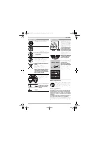
Starting Operation
Observe the mains voltage!
The voltage of the power
source must correspond with the data on the type plate of
the machine.
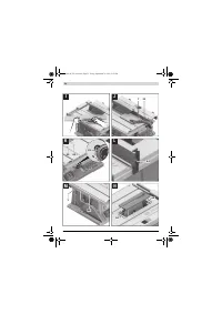
Starting and Stopping (see figure G)
–
To start
the operation, press the green ON button
14
.
–
To stop
the operation, press the red OFF button
15
.
When not using the power tool, switch it off in order to save
energy.
Power Failure
The ON/OFF switch is a so-called non-voltage switch, which
prevents the power tool from restarting after a power failure
(e. g., when the mains plug is pulled during operation).
To restart the operation of the machine afterwards, the green
ON button
14
must be pressed again.
Working Advice
General Sawing Instructions
For all cuts, it must first be ensured that the saw blade
at no time can come in contact with the stops or other
machine parts.
Use the machine for grooving or rebating only with an
appropriately suitable protective device (e. g. a tunnel
blade guard).
Do not use the machine for cutting slots (stopped
grooves).
Do not saw workpieces that contain nails, screws or
other metal objects.
The machine is designed only for
sawing wood. Before sawing, remove any foreign materials
from the workpiece. Otherwise there is danger of fire.
Always use dust extraction.
Protect the saw blade against impact and shock. Do not sub-
ject the saw blade to lateral pressure.
The riving knife must be in alignment with the saw blade to
avoid jamming of the workpiece.
Do not saw warped/bent workpieces. The workpiece must al-
ways have a straight edge to face against the parallel guide.
Always keep/store the push stick with the power tool.
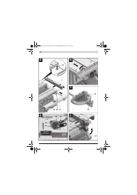
Marking the Cutting Line
– Mark the saw blade width on the round yellow sticker
6
.
This allows for exact positioning of the workpiece for saw-
ing, without having to open the blade guard.
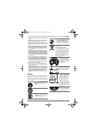
Position of the Operator (see figure H)
Do not stand in a line with the saw blade in front of the
machine. Always stand aside of the saw blade.
This pro-
tects your body against possible kickback.
– Keep hands, fingers and arms away from the rotating saw
blade.
Observe the following instructions:
– Hold the workpiece securely with both hands and press it
firmly against the saw table, expecially when working with-
out the guide. (see figure I)
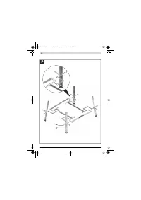
– When sawing narrow workpieces and bevel angles, always
use the supplied push stick
22
and the auxiliary stop
7
.
(see figure J)
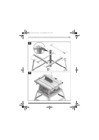
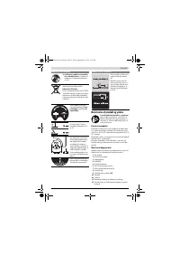
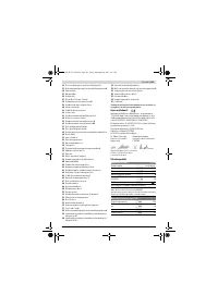
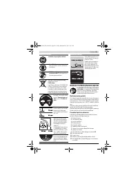
Maximum Workpiece Dimensions
Sawing
Sawing Straight Cuts
– Adjust the parallel guide
8
to the requested cutting width.
– (see “Adjusting the Parallel Fences”, page 34)
– Position the workpiece on the saw table in front of the
blade guard
5
.
– Raise or lower the saw blade with the crank
12
so that the
upper saw teeth project approx. 5 mm above the work-
piece surface.
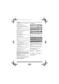
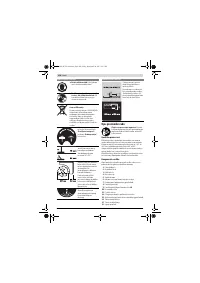
Bevel angle
Max. workpiece height
[mm]
0 °
75
45 °
63
OBJ_BUCH-783-006.book Page 34 Friday, September 28, 2012 2:27 PM
Содержание
- 202 Применение электроинструмента и обращение с ним
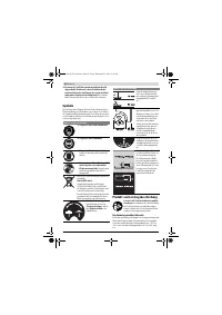
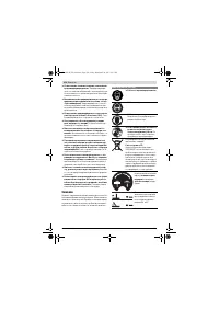
- 203 Символы; Символы и их значение
- 204 Описание продукта и услуг; Применение по назначению
- 205 Технические данные; Применяйте средства защиты органов слуха!; Заявление о соответствии; Сборка; Комплект поставки; В исполнениях электроинструмента с подставкой; Размеры пильных дисков
- 206 Первое включение; Последовательность монтажа; Монтаж снизу
- 207 Отсос пыли и стружки; Избегайте скопления пыли на рабочем месте.; Стационарный или временный монтаж
- 208 Работа с инструментом; Увеличение площади стола
- 209 Настройка параллельных упоров
- 210 Максимальные размеры заготовки; Пиление; Выполнение прямых пропилов; Основные настройки – контроль и коррекция; Настройка угла наклона в 0 °
- 211 Хранение электроинструмента; Техобслуживание и сервис; Техобслуживание и очистка; Очистка; Принадлежности; Товарный No
- 212 Россия; Утилизация


