Электропилы Bosch PTS 10 - инструкция пользователя по применению, эксплуатации и установке на русском языке. Мы надеемся, она поможет вам решить возникшие у вас вопросы при эксплуатации техники.
Если остались вопросы, задайте их в комментариях после инструкции.
"Загружаем инструкцию", означает, что нужно подождать пока файл загрузится и можно будет его читать онлайн. Некоторые инструкции очень большие и время их появления зависит от вашей скорости интернета.


English |
35
Bosch Power Tools
1 609 92A 039 | (28.9.12)
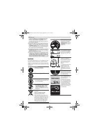
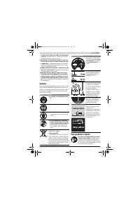
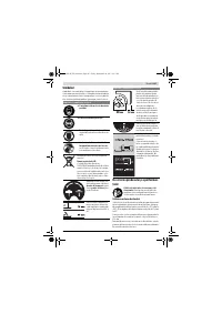
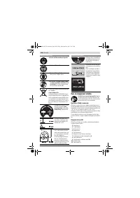
Note:
Take care that the blade guard is properly positioned.
When sawing, it must always face against the workpiece.
– Switch on the machine.
– Saw through the workpiece applying uniform feed.
– Switch off the machine and wait until the saw blade has
come to a complete stop.
Sawing Bevel Angles
– Adjust the desired bevel angle. (see “Adjusting Bevel An-
gles”, page 33)
– Follow the worksteps in section “Sawing Straight Cuts” ac-
cordingly.
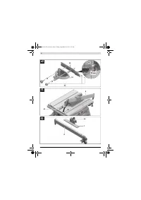
Adjusting the Clearance between Saw Blade and Auxiliary
Stop on the Angle Stop (see figure e2)
The clearance between saw blade and auxiliary stop
18
must
not exceed 15 mm (max.).
– When the auxiliary stop
18
is behind the cutting line, loos-
en both screws of fastening kit
43
.
– Move the auxiliary stop and tighten the screws again.
Sawing Mitre Angles with the Sliding Table Locked
– Adjust the requested mitre angle. (see “Adjusting Mitre An-
gles”, page 33)
– The angle stop must move freely in the guide groove
21
(leftward or rightward). For this, loosen locking knob
42
, if
required.
– Follow the worksteps in section “Sawing Straight Cuts” ac-
cordingly.
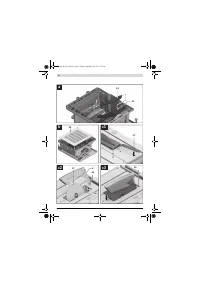
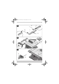
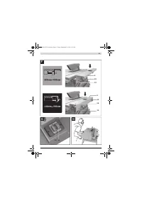
Sawing Mitre Angles with the Sliding Table
– Adjust the requested mitre angle. (see “Adjusting Mitre An-
gles”, page 33)
– Tilt the locking lever
24
toward the right and push the slid-
ing table
1
toward the front. (see figure B)
– Position the workpiece on the saw table in front of the
blade guard
5
.
– Position the angle stop
16
in front of the workpiece in the
lefthand guide groove
21
. Lock this position by firmly
tightening locking knob
42
.
– Follow the worksteps in section “Sawing Straight Cuts” ac-
cordingly.
Checking and Adjusting the Basic Adjustment
To ensure precise cuts, the basic adjustment of the machine
must be checked and adjusted as necessary after intensive
use.
A certain level of experience and appropriate specialty tools
are required for this.
A Bosch after-sales service station will handle this mainte-
nance task quickly and reliably.
Setting the Standard Bevel Angle 0 ° (Vertical)
– Adjust a 0 ° bevel angle.
Checking:
– Set an angle gauge to 90 ° and place it on the saw table
11
.
The leg of the angle gauge must be flush with the saw blade
37
over the complete length.
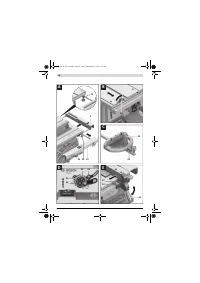
Adjusting:
(see figure K)
– Loosen the locking knob
29
and hold the saw blade with
help of the handwheel
54
in the 90° position.
– Loosen adjusting screw
59
and lightly retighten the locking
knob
29
.
– Screw the adjusting screw in or out until the leg of the angle
gauge is flush with the saw blade over the complete length.
– Afterwards, firmly tighten the locking knob
29
again.
When the angle indicator
55
is not in line with the 0 ° mark of
scale
56
, loosen screw
61
with a commercially available Phil-
lips screwdriver and align the angle indicator alongside the 0 °
mark.
Setting the Standard Bevel Angle 45 ° (Vertical)
(see figure K)
– Repeat the above mentioned worksteps accordingly for
the 45 ° bevel angle:
Loosen locking knob
29
,
adjust the adjusting screw
60
.
In this, the angle indicator
55
must not be readjusted.
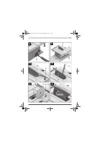
Adjusting the Tension Force of the Parallel Guide
(see figure L)
The tensioning force of the parallel guide
8
can decrease after
frequent usage.
– Tighten nut
62
until the parallel fence can be firmly locked
to the saw table again.
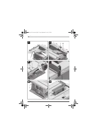
Adjusting the Play of the Sliding Table (see figure M)
– When the play of the sliding table
1
becomes too large after
frequent usage, tighten the adjusting screws
63
.
Adjusting the Level of the Insert Plate (see figure N)
Checking:
The front side of the insert plate
3
must be flush with or some-
what lower than the saw table; the rear side must be flush with
or somewhat above the saw table.
Adjusting:
– Adjust the correct level with help of the four adjusting
screws
64
.
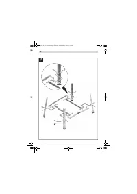
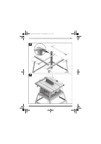
Storage and Transport (see figure O)
Storing the Power Tool
For storage purposes, the hold-down stick, stops/guides and
spare saw blades can be securely fastened to the power tool.
– Bring the machine into the transport position. (see “Trans-
port Position”, page 33)
– Undo auxiliary stop
7
from parallel guide
8
and auxiliary
stop
18
from angle stop
16
.
– Insert the guide/stops
8
,
16
and
18
into their correspond-
ing storage compartments and fasten push stick
22
.
– Wind the mains cable around the cable holder
30
.
– A spare saw blade can be fastened to the machine housing
for storage with help of the fastening screw
19
.
OBJ_BUCH-783-006.book Page 35 Friday, September 28, 2012 2:27 PM
Содержание
- 202 Применение электроинструмента и обращение с ним
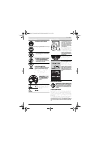
- 203 Символы; Символы и их значение
- 204 Описание продукта и услуг; Применение по назначению
- 205 Технические данные; Применяйте средства защиты органов слуха!; Заявление о соответствии; Сборка; Комплект поставки; В исполнениях электроинструмента с подставкой; Размеры пильных дисков
- 206 Первое включение; Последовательность монтажа; Монтаж снизу
- 207 Отсос пыли и стружки; Избегайте скопления пыли на рабочем месте.; Стационарный или временный монтаж
- 208 Работа с инструментом; Увеличение площади стола
- 209 Настройка параллельных упоров
- 210 Максимальные размеры заготовки; Пиление; Выполнение прямых пропилов; Основные настройки – контроль и коррекция; Настройка угла наклона в 0 °
- 211 Хранение электроинструмента; Техобслуживание и сервис; Техобслуживание и очистка; Очистка; Принадлежности; Товарный No
- 212 Россия; Утилизация


